US Patent No. 9,413,125

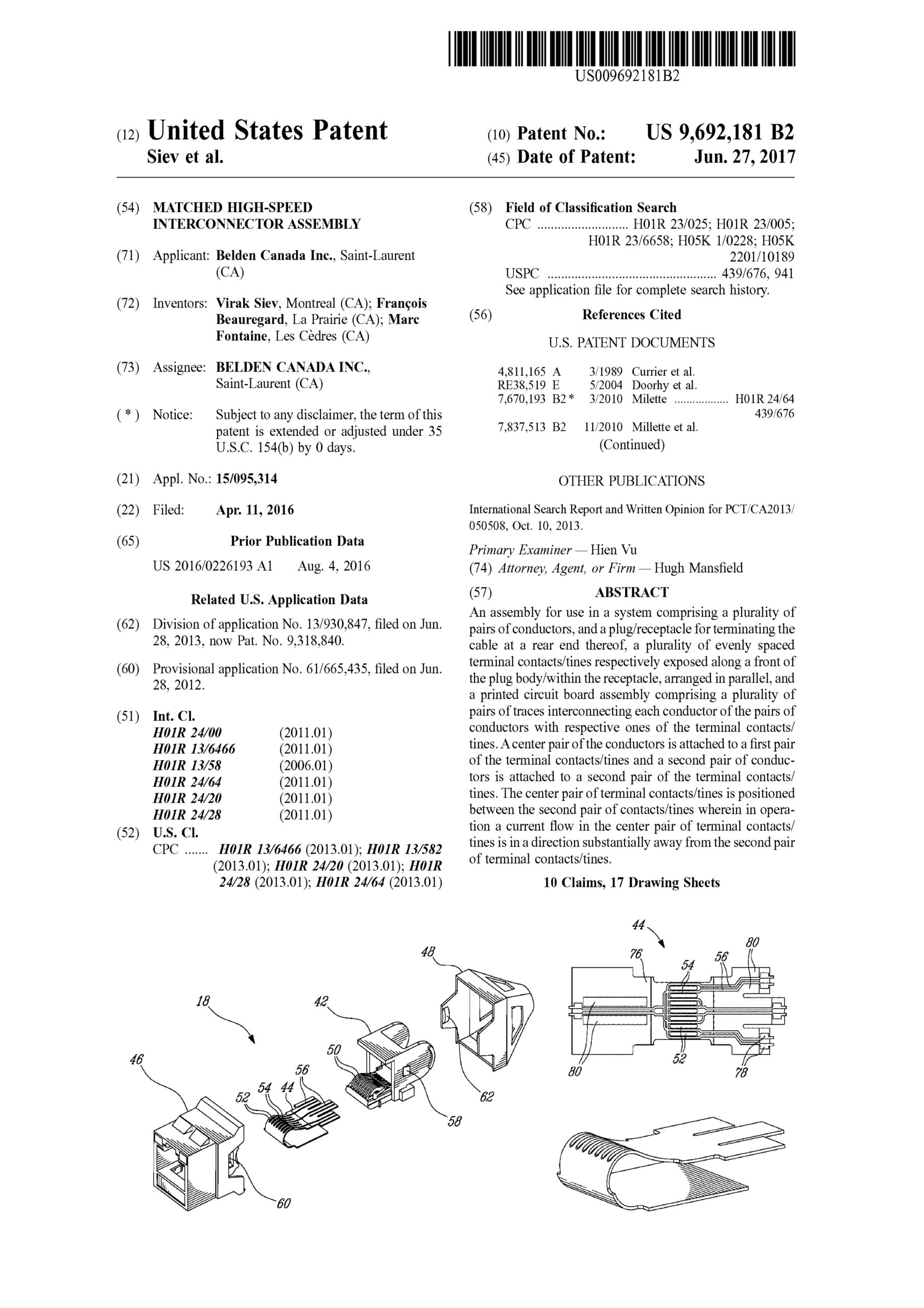
Coupler connector and cable terminator with end contacts

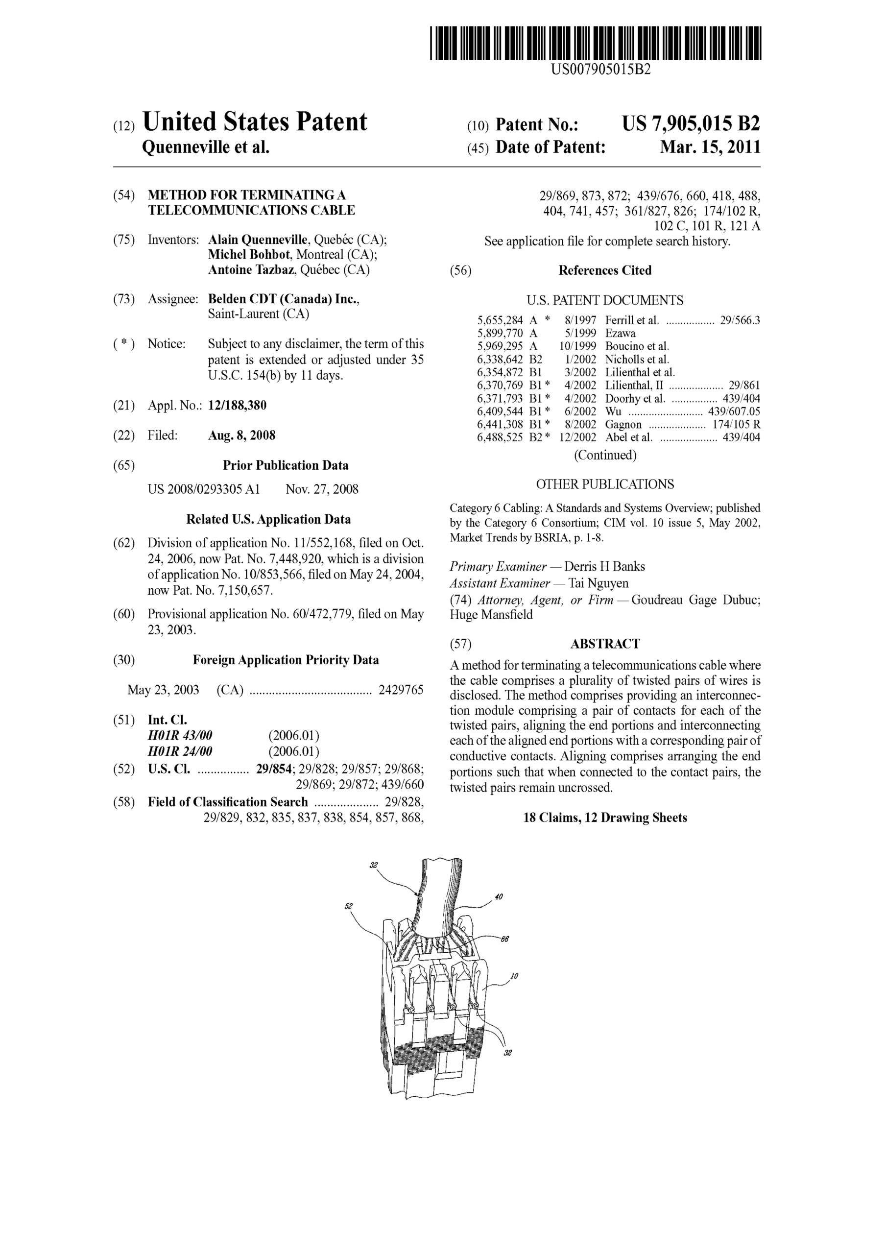
An assembly comprising a cable terminator comprising an elongate wire guide comprising a top end and four conductor pair receiving channels, and a securing cap configured for installation over the top end and comprising four pairs of piercing contacts exposed on an upper surface is disclosed. Each pair of the piercing contacts are interconnected with a respective conductor pair, and a coupler connector comprising a forward surface comprising an RJ-45 compatible socket, wherein tines are exposed within the socket and a rearward surface comprising a cable terminator receiving socket. Pairs of contacts are exposed on an end wall of the socket. Each of the tines is interconnected with a respective one of the contacts. When the cable terminator is inserted into the cable terminator receiving socket, the upper surface of the securing cap is positioned against the end wall and each of the piercing contacts comes into contact with a respective one of the contacts, thereby interconnecting each of the tines with one of the conductors.

US Patent No. 9,692,181

Matched high-speed interconnector assembly

An assembly for use in a system comprising a plurality of pairs of conductors, and a plug/receptacle for terminating the cable at a rear end thereof, a plurality of evenly spaced terminal contacts/tines respectively exposed along a front of the plug body/within the receptacle, arranged in parallel, and a printed circuit board assembly comprising a plurality of pairs of traces interconnecting each conductor of the pairs of conductors with respective ones of the terminal contacts/tines. A center pair of the conductors is attached to a first pair of the terminal contacts/tines and a second pair of conductors is attached to a second pair of the terminal contacts/tines. The center pair of terminal contacts/tines is positioned between the second pair of contacts/tines wherein in operation a current flow in the center pair of terminal contacts/tines is in a direction substantially away from the second pair of terminal contacts/tines.

US Patent No. 8,801,298

Slide actuated field installable fiber optic connector

A connector assembly for reversibly terminating a fiber optic cable comprising an optical fiber stub and an actuator illustratively configured for sliding along a path between a first position and a second position which illustratively serves to move one or more anvils thereby mechanically clamping the fiber optic cable proximate to the optical fiber stub.

US Patent No. 8,075,198

Reversible fiber connector with mechanical sliding splice

A connector assembly for reversibly terminating an optical fiber comprises a housing having a cavity extending along a longitudinal axis. An elongate member having a groove extending along a surface thereof is provided within the cavity. An end portion of the fiber is aligned with a fiber stub within the groove such that the stub’s splicing face is positioned opposite the fiber’s splicing face. A splice anvil is mounted about the member with the anvil’s clamping surface overlapping the abutting stub and fiber splicing faces. The clamping mechanism comprises step surfaces arranged along the member’s surface adjacent the groove. When the anvil is moved from the released position to the clamped position, the anvil’s inner surface is moved along the step surfaces in a direction perpendicular to the longitudinal axis towards the groove, the anvil’s clamping surface bringing a clamping force to bear on the abutting fiber and fiber stub.

US Patent No. 8,141,224

Patch panel labelling system

The present invention provides a patch panel labelling system for mounting to a telecommunications rack. The system comprises a connector module mounted to the rack and having a front face with a plurality of connectors. A labelling plate is mounted to the module for movement about a first pivot axis between a first position where the plate is substantially parallel to the front face of the module and a second position where the plate is pivoted away from the front face for providing access to the connectors. The plate can be further pivoted about a second pivot axis to selectively hide or reveal the labels provided thereon for identifying the connectors. The plate can be also be slid underneath the module for storage.

US Patent No. 8,167,662

Cable comprising connector with insulation piercing contacts

There is disclosed a connector and method for terminating a cable comprised twisted pairs of conductors. In one aspect of the invention the connector comprises a wire lead guide for arranging the twisted pairs of conductors and a plurality of piercing contacts which interconnect with respective ones of the twisted pairs of conductors when the wire guide is secured to the module. In a further aspect of the invention the wire lead guide ensures that the spacing between the conductors of a particular twisted pair is maintained, thereby improving the performance of the subsequent assembly.

US Patent No. 8,021,197

Telecommunications connector

A contact element and mechanism for use in a connector, the connector comprising a socket adapted for receiving a cable plug comprising a terminal contact. The contact element and mechanism comprise a flexible dielectric substrate and a first conductive strip on a first surface of the substrate. When the plug is inserted into the socket, the terminal contact comes into contact with the conductive strip.
There is also provided a compensating connector for interconnection with a cable plug, the plug comprising a plurality of terminal contacts. The connector comprises a socket adapted for receiving the plug, a plurality of contact elements disposed in the socket, each of the contact elements comprising a conductive strip, and a compensation network comprised of a plurality of compensating elements. Each of the compensating elements is located adjacent to one of the contact elements. When the plug is inserted into the socket, each of the terminal contacts comes into contact with a predetermined one of the conductive strips.

US Patent No. 6,780,035

Electrostatic discharge protected jack

A method and apparatus for discharging accumulated static charge in unshielded twisted pair cables. According to one example, an electrical jack includes a housing having an opening defined therein through which a mating plug is received, a grounding strip, and at least one elastically deformable signal contact residing within the housing. As the mating plug is received, the elastically deformable signal contact may move from a position in contact with the grounding strip to a position not in contact with the grounding strip, thereby discharging static charge from the unshielded twisted pair cables and allowing normal connection to the mating plug.

US Patent No. 7,258,493

Keyed fibre optic connector

A keying system for providing selective interconnection between a receptacle socket and a connector plug terminating an optic fibre, the connector plug adapted for insertion into the receptacle socket. The keying system comprises a raised boss configured to one of a plurality of predefined boss keying geometries and a cavity configured to one of a plurality of predefined cavity keying geometries. The boss is either in one of the receptacle socket or on a forward end of the connector plug and the cavity is formed in the other of the receptacle socket or the forward end of the connector plug. At least one of the predefined boss keying geometries matches at least one of the predefined cavity keying geometries. When the boss keying geometry matches the cavity keying geometry, the boss can be inserted into the cavity thereby interconnecting the connector plug with the receptacle socket. In this manner correct interconnections between connectors and other connectors or sockets can be insured thereby providing an enhanced level of security.

US Patent No. 7,905,015

Method for terminating a telecommunications cable

A method for terminating a telecommunications cable where the cable comprises a plurality of twisted pairs of wires is disclosed. The method comprises providing an interconnection module comprising a pair of contacts for each of the twisted pairs, aligning the end portions and interconnecting each of the aligned end portions with a corresponding pair of conductive contacts. Aligning comprises arranging the end portions such that when connected to the contact pairs, the twisted pairs remain uncrossed.