US Patent No. 10,186,797

Coupler connector and cable terminator with side contacts

An assembly comprising a cable terminator comprising a wire guide, a cube shaped securing cap comprising an open end for installation over the wire guide, and pairs of piercing contacts for piercing respective conductors of the cable. When assembled, an outer end of each of the piercing contacts is exposed on an outer surface of a respective securing cap sidewall. The assembly also comprises a coupler connector comprising one of a modular (for example RJ-45 compatible) socket or a modular (for example RJ-45 compatible) plug, a rearward surface comprising a cable terminator receiving socket, wherein pairs of contacts are exposed along at least one side wall of the socket, and further wherein each of a plurality of the tines in the modular socket or the terminal contacts of the plug is interconnected with a respective one of the contacts.

US Patent No. 10,185,108

Dual direction fiber optic cassette system and fiber optic cassette with removable standalone adaptor plate

An optic fiber system for mounting in a rack, cassette and front plate are disclosed. A fiber optic cassette receives a pair of opposed rails on opposite inner surfaces of a housing. Catches on the fiber optic cassette comprise biased tabs which engage grooves within the rails thereby releasable securing the cassette into the housing. Catches may be provided at both ends of the cassette allowing the cassette to be inserted from either end of the housing. The cassette comprises removable front plate which is secured to it using a snap fit. The removable plate can be used either with the cassette or as a standalone within the housing.

US Patent No. 10,185,101

Plug with rotatable release mechanism

A plug assembly comprising at least one elongate ferrule terminating an one optic fiber and arranged in parallel to an actuating axis, a plug housing the ferrule and such that an end of the ferrule is exposed at a forward end thereof, the forward end configured for insertion into a receptacle, an elongate release lever for releasably securing the plug housing to the receptacle, the lever comprising a first end fixed to the plug housing towards the forward end and a flexible free end, and an actuating assembly cooperating with the flexible free end and rotatable about the actuating axis between a position where the flexible free end is positioned spaced from the housing and a position where the flexible free end is positioned immediately adjacent the housing.

US Patent No. 9,841,574

Deformable latch mechanism for tray

A latch mechanism for retaining a tray in a selected one of a first, second position and third position. The latch mechanism comprises notches arranged on an inner surface of the housing along an axis parallel to a direction of travel of the tray, an elongate actuator on the tray and opposite the inner surface, the actuator comprising a first elongate member and a second elongate member, an inner end of the first elongate member connected to an inner end of the second elongate member at a connection point, a stop positioned at the connection point wherein the stop is biased laterally towards the inner surface. By increasing a distance between an outer end of the first elongate member and an outer end of the second elongate member the stop is moveable from an unactuated state wherein the stop is engageable by a selected one of the notches and such that the tray is retainable in a selected one of the first, second and third position, to an actuated state wherein the stop moves laterally against the biasing force away from the inner surface and such that the stop is no longer engageable by one of the notches.
US Patent No. 9,865,975

Hinged connector door assembly

A door assembly for attachment to a connector housing is shown. The door assembly comprises a pair of opposed doors mounted on either side of an opening by a hinge, which when in a closed position define a cable receiving opening there between. Supports are provided on either door which grip the of cable therebetween when the doors are in the closed position. In a particular embodiment a locking mechanism is provided to retain the doors in a closed.

US Patent No. 9,577,396

Keystone jack adaptor

An adaptor for receiving a keystone type connector and insertion into a patch panel is provided, having a bottom wall with a ridge engaging lower slot and a lower edge engaging channel and a top wall having a flexible tab and a cantilevered latch engaging upper slot and an upper edge engaging channel in the flexible tab. The walls define a keystone modular jack receiving region and opening. The adaptor is dimensioned such that when the lower edge is received in the lower edge engaging channel, the upper edge is releasably engageable by the upper edge engaging channel, thereby releasably securing the adaptor within an aperture in a patch panel.

US Patent No. 9,570,852

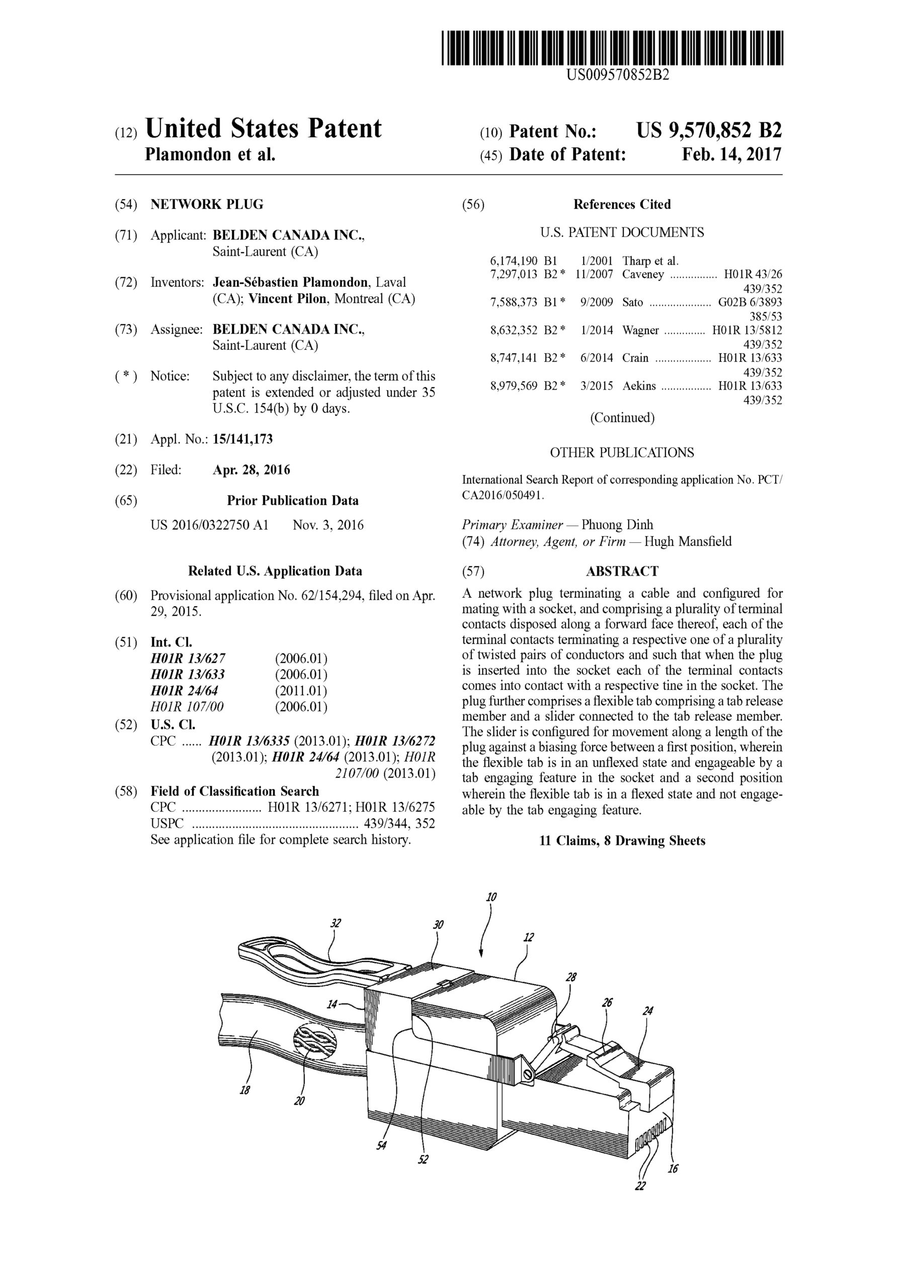
Network plug

A network plug terminating a cable and configured for mating with a socket, and comprising a plurality of terminal contacts disposed along a forward face thereof, each of the terminal contacts terminating a respective one of a plurality of twisted pairs of conductors and such that when the plug is inserted into the socket each of the terminal contacts comes into contact with a respective tine in the socket. The plug further comprises a flexible tab comprising a tab release member and a slider connected to the tab release member. The slider is configured for movement along a length of the plug against a biasing force between a first position, wherein the flexible tab is in an unflexed state and engageable by a tab engaging feature in the socket and a second position wherein the flexible tab is in a flexed state and not engageable by the tab engaging feature.

US Patent No. 9,397,455

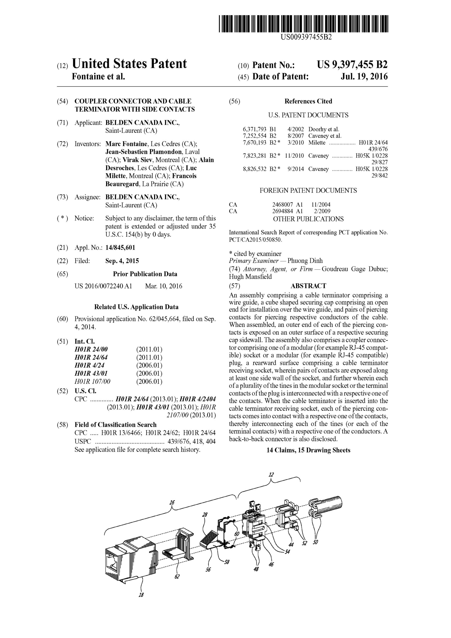
Coupler connector and cable terminator with side contacts

An assembly comprising a cable terminator comprising a wire guide, a cube shaped securing cap comprising an open end for installation over the wire guide, and pairs of piercing contacts for piercing respective conductors of the cable. When assembled, an outer end of each of the piercing contacts is exposed on an outer surface of a respective securing cap sidewall. The assembly also comprises a coupler connector comprising one of a modular (for example RJ-45 compatible) socket or a modular (for example RJ-45 compatible) plug, a rearward surface comprising a cable terminator receiving socket, wherein pairs of contacts are exposed along at least one side wall of the socket, and further wherein each of a plurality of the tines in the modular socket or the terminal contacts of the plug is interconnected with a respective one of the contacts. When the cable terminator is inserted into the cable terminator receiving socket, each of the piercing contacts comes into contact with a respective one of the contacts, thereby interconnecting each of the tines (or each of the terminal contacts) with a respective one of the conductors. A back-to-back connector is also disclosed.

US Patent No. 9,865,960

Coupler connector and cable terminator with side contacts

An assembly comprising a cable terminator comprising a wire guide, a cube shaped securing cap comprising an open end for installation over the wire guide, and pairs of piercing contacts for piercing respective conductors of the cable. When assembled, an outer end of each of the piercing contacts is exposed on an outer surface of a respective securing cap sidewall. The assembly also comprises a coupler connector comprising one of a modular (for example RJ-45 compatible) socket or a modular (for example RJ-45 compatible) plug, a rearward surface comprising a cable terminator receiving socket, wherein pairs of contacts are exposed along at least one side wall of the socket, and further wherein each of a plurality of the tines in the modular socket or the terminal contacts of the plug is interconnected with a respective one of the contacts. When the cable terminator is inserted into the cable terminator receiving socket, each of the piercing contacts comes into contact with a respective one of the contacts, thereby interconnecting each of the tines (or each of the terminal contacts) with a respective one of the conductors. A back-to-back connector is also disclosed.