US Patent No. 7,699,533

Back-to-back receptacle

A back-to-back receptacle and system for providing selective interconnection between a pair of optic fibres. The system comprises a receptacle comprising a pair of back-to-back receptacle sockets, with at least a first of the sockets configured to one of a plurality of predefined receptacle keying geometries, a first connector plug terminating the first optic fibre, the plug adapted for insertion into the first receptacle socket, the plug configured to one of a plurality of predefined connector keying geometries and a second connector plug terminating the second optic fibre, the plug adapted for insertion into a second of the back-to-back receptacle sockets. At least one of the predefined connector keying geometries matches at least one of the predefined receptacle keying geometries. When the receptacle keying geometry of the first receptacle socket corresponds to the connector keying geometry of the first plug and optionally the receptacle geometry of the second of the back-to-back receptacle sockets corresponds to the connector keying geometry of the second plug, the first plug can be inserted in the first socket and the second plug can be inserted in the second socket bringing the first optic fibre into axial alignment with the second optic fibre.
US Patent No. 7,674,046

Fibre optic connector keying system

A keying system for providing selective interconnection between a receptacle socket and a connector plug terminating an optic fibre, the connector plug adapted for insertion into the receptacle socket. The keying system comprises a raised boss configured to one of a plurality of predefined boss keying geometries and a cavity configured to one of a plurality of predefined cavity keying geometries. The boss is either in one of the receptacle socket or on a forward end of the connector plug and the cavity is formed in the other of the receptacle socket or the forward end of the connector plug. At least one of the predefined boss keying geometries matches at least one of the predefined cavity keying geometries. When the boss keying geometry matches the cavity keying geometry, the boss can be inserted into the cavity thereby interconnecting the connector plug with the receptacle socket. In this manner correct interconnections between connectors and other connectors or sockets can be insured thereby providing an enhanced level of security.

US Patent No. 7,150,657

Wire lead guide and method for terminating a communications cable

A method for terminating a telecommunications cable where the cable comprises a plurality of twisted pairs of wires. The method comprises the steps providing an interconnection module comprising a pair of contacts for each of the twisted pairs, aligning the end portions and interconnecting each of the aligned end portions with a corresponding pair of conductive contacts. The aligning step comprises arranging the end portions such that when connected to the contact pairs, the twisted pairs remain uncrossed.
A wire lead guide for isolating the end portions of a plurality twisted pairs of wires an a connector assembly using the same. The guide comprises a guide body and a plurality of non-intersecting passageways through the body. Each of the passageways is comprised of an entrance and an exit. The end portions of one of the twisted pairs are inserted through a corresponding one of the passageways. The passageways isolate the twisted pairs of wires from one another.

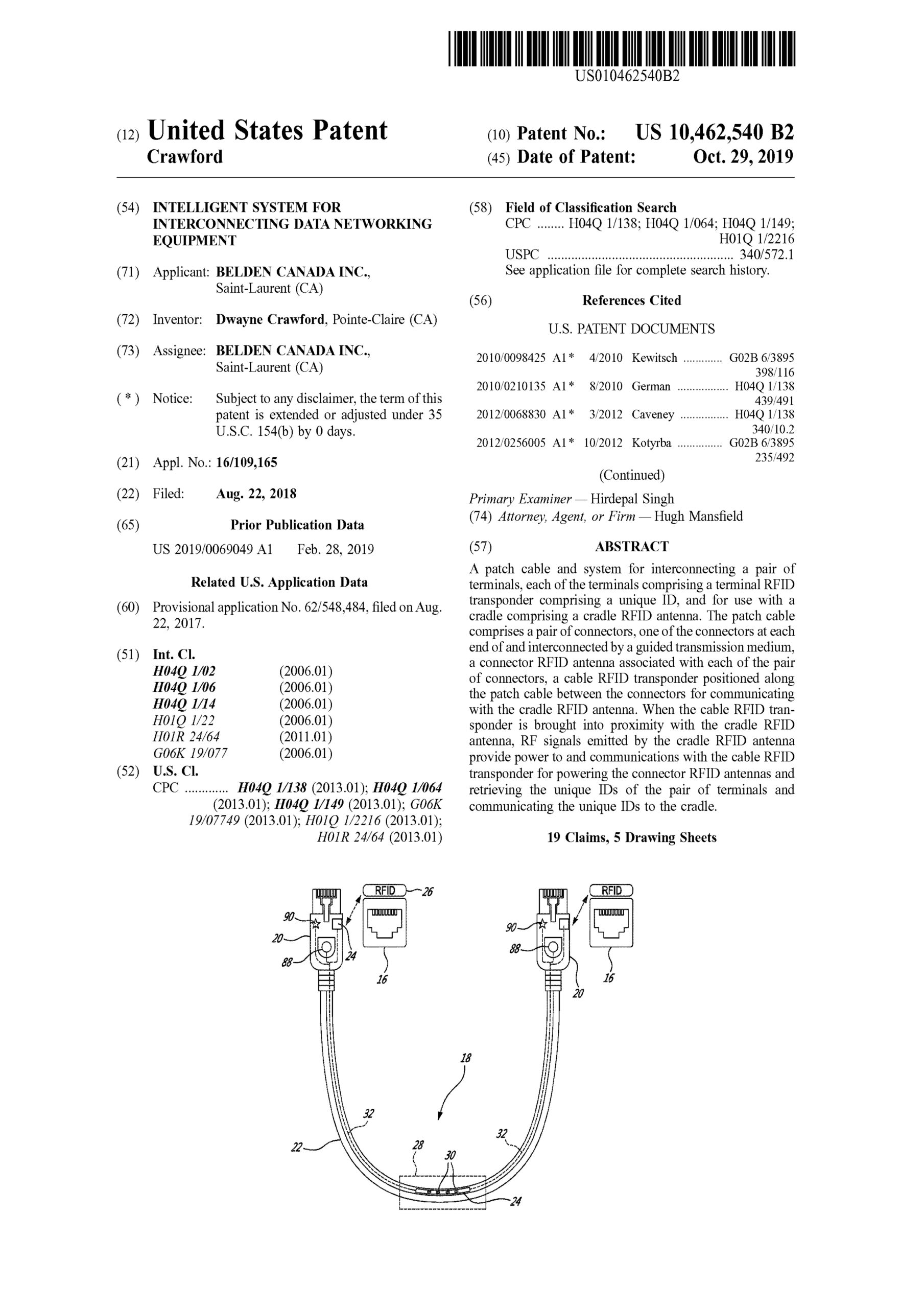
US Patent No. 10,462,540

Intelligent system for interconnecting data networking equipment

A patch cable and system for interconnecting a pair of terminals, each of the terminals comprising a terminal RFID transponder comprising a unique ID, and for use with a cradle comprising a cradle RFID antenna. The patch cable comprises a pair of connectors, one of the connectors at each end of and interconnected by a guided transmission medium, a connector RFID antenna associated with each of the pair of connectors, a cable RFID transponder positioned along the patch cable between the connectors for communicating with the cradle RFID antenna. When the cable RFID transponder is brought into proximity with the cradle RFID antenna, RF signals emitted by the cradle RFID antenna provide power to and communications with the cable RFID transponder for powering the connector RFID antennas and retrieving the unique IDs of the pair of terminals and communicating the unique IDs to the cradle.

US Patent No. 10,473,859

Fiber optic connector

A fiber optic connector comprising a fusion assembly for strengthening a splice point. The fusion assembly comprises an elongate mechanical support positioned adjacent the splice point and snugly encased by a flexible tube. In one embodiment, a meltable adhesive in the form of a hollow tube is positioned over the splice point and the flexible tube comprises a heat shrinkable material. In another embodiment, the mechanical support is an elongate plate having a concave surface positioned adjacent the splice point and a C shaped cross section.

US Patent No. 10,175,430

Overmoulded furcation assembly with strain relief

An assembly comprises an optic cable comprising a plurality of optic fiber subunits each comprising at least one optic fiber encased in a fiber jacket and a plurality of aramid strands is disclosed. The assembly further comprises one or more blocks comprising a passage ways for receiving the optic fiber subunits and maintaining adjacent ones of the optic fiber subunits at a predetermined spacing. A housing is molded over the open end of the cable jacket, the aramid strands and the first end of the at least one block. A method of overmolding a transition between an optic fiber cable and a furcation jacketing is also disclosed wherein a mold comprises ribs arranged at right angles to an axis of the mold and such that aramid strands are prevented during injecting from reaching a surface of the mold.

US Patent No. 10,250,000

Cable assembly tool

A tool comprising a receptacle for receiving and holding a cable terminating assembly comprising a plurality of conductors and a plurality of piercing contacts, the tool comprising a pair of handles which actuate opposed presses and blades, the presses pushing the piercing contacts into the conductors while the blades trim the ends of the conductors.

US Patent No. 10,103,493

Method of maintaining cross talk in different zones of an assembly for interconnecting a cable

A method of manufacturing a connector and assembly of a cabling category and comprising two mating zones connected by an intermediate zone. Each of the zones is manufactured such that Near End Cross Talk (NEXT) resulting from transmission of the high frequency signal across each zone is below a specified amount chosen such that NEXT introduced by a high frequency signal transmission between via all the zones is below a level as specified for the cabling category.

US Patent No. 8,376,631

Slide Actuated Field Installable Fiber Optic Connector

A connector assembly for reversibly terminating a fiber optic cable comprising an optical fiber stub and an actuator illustratively configured for sliding along a path between a first position and a second position which illustratively serves to move one or more anvils thereby mechanically clamping the fiber optic cable proximate to the optical fiber stub.

US Patent No. 7,448,920

Wire Lead Guide and Method for Terminating a Communications Cable

A method for terminating a telecommunications cable where the cable comprises a plurality of twisted pairs of wires. The method comprises the steps providing an interconnection module comprising a pair of contacts for each of the twisted pairs, aligning the end portions and interconnecting each of the aligned end portions with a corresponding pair of conductive contacts. The aligning step comprises arranging the end portions such that when connected to the contact pairs, the twisted pairs remain uncrossed.
A wire lead guide for isolating the end portions of a plurality twisted pairs of wires and a connector assembly using the same. The guide comprises a guide body and a plurality of non-intersecting passageways through the body. Each of the passageways is comprised of an entrance and an exit. The end portions of one of the twisted pairs are inserted through a corresponding one of the passageways. The passageways isolate the twisted pairs of wires from one another.