US Patent No. 7,887,244

Reversible fiber connector with mechanical splice and sliding lock

A connector assembly for reversibly terminating an optical fiber comprises a housing having a cavity extending along a longitudinal axis. An elongate member having a groove extending along a surface thereof is provided within the cavity. An end portion of the fiber is aligned with a fiber stub within the groove such that the stub’s splicing face is positioned opposite the fiber’s splicing face. A splice anvil is positioned adjacent the member’s surface with the anvil’s clamping surface overlapping the abutting stub and fiber splicing faces. The clamping mechanism comprises an actuator slideably mounted about the member for movement between a released position and a clamping position in which the inner surface of the actuator displaces the anvil in a direction perpendicular to the longitudinal axis and towards the member’s surface, the anvil’s clamping surface thus bringing a clamping force to bear on the abutting fiber and fiber stub.

US Patent No. 7,811,006

Field installable fiber optic connector and installation tool

A connector for reversibly terminating a cable comprising a buffer cladding surrounding an optical fiber wherein an end portion of the cable is exposed to reveal the optical fiber. The connector comprises a clamping assembly comprising a splice anvil comprising a fiber clamping surface positioned facing a member surface and overlapping a stub splicing face and an optical fiber splicing face. The clamping assembly is adapted for opening by applying a tangential force to the splice anvil, illustratively through engaging an actuating boss with a tool inserted through the opening and applying a force to the actuating boss such that the clamping surface is moved away from the member surface against a spring.

US Patent No. 7,645,160

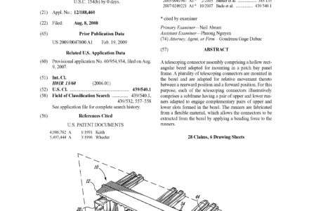
Telescoping connector assembly

A telescoping connector assembly comprising a hollow rectangular bezel adapted for mounting in a patch bay panel frame. A plurality of telescoping connectors are mounted in the bezel and are adapted for relative movement thereto between a rearward position and a forward position. For this purpose, each of the telescoping connectors illustratively comprises a subframe having a pair of upper and lower runners adapted to engage complementary pairs of upper and lower slots formed in the bezel. The runners are fabricated from a flexible material, which allows the connectors to be extracted from the bezel by applying a bending force to the runners.

US Patent No. 10,928,603

Patch panel system with tiltable tray and multiposition lock and release mechanism

A patch panel system is disclosed comprising a plurality of trays wherein each tray is stored within a patch panel housing but moveable towards the front of the housing into one of a patch position or an extended position. The tray is lockable in either the patch position or the extended position. In the extended position a front tray section holding one or more fiber optic connectors or modules is tiltable versus a rear tray section. In particular embodiment the tray can also be moved from the stored position into a retracted position behind the housing. A release mechanism comprising a lock is also provided which can be actuated to release the lock thereby allowing the tray to be slid out of the patch position and the extended position.

US Patent No. 10,866,379

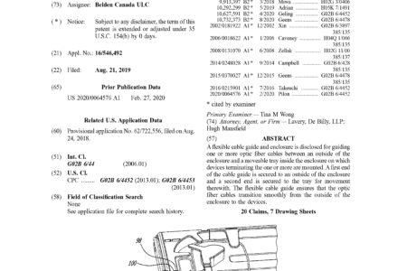
Flexible cable guide

A flexible cable guide and enclosure is disclosed for guiding one or more optic fiber cables between an outside of the enclosure and a moveable tray inside the enclosure on which devices terminating the one or more are mounted. A first end of the cable guide is secured to an outside of the enclosure and a second end is secured to the tray for movement therewith. The flexible cable guide ensures that the optic fiber cables transition smoothly from the outside of the enclosure to the devices.

US Patent No. 10,809,479

Fiber optic cassette system with reversible cassettes

A reversible fiber optic cassette for mounting with other like cassettes in a rack comprising a cassette receiving tray, the tray comprising a plurality of cassette engaging features on an upper surface is disclosed. The cassette comprises N duplex pairs of optic fiber receptacles arranged along a front thereof, a multifiber receptacle on a back thereof and 2*N optic fiber segments each between a respective one of the optic fiber receptacles and the multifiber receptacle, N discrete port identifiers on a first surface thereof and N discrete port identifiers on a second surface opposite the first surface. The first set of N identifiers is the same as the second set of N identifiers and for M between 1 to N, an Mth port identifier of the first set and an (N-M+1)th port identifier of the second set is adjacent an Mth one of the duplex pairs of optic fiber receptacles.

US Patent No. 10,795,107

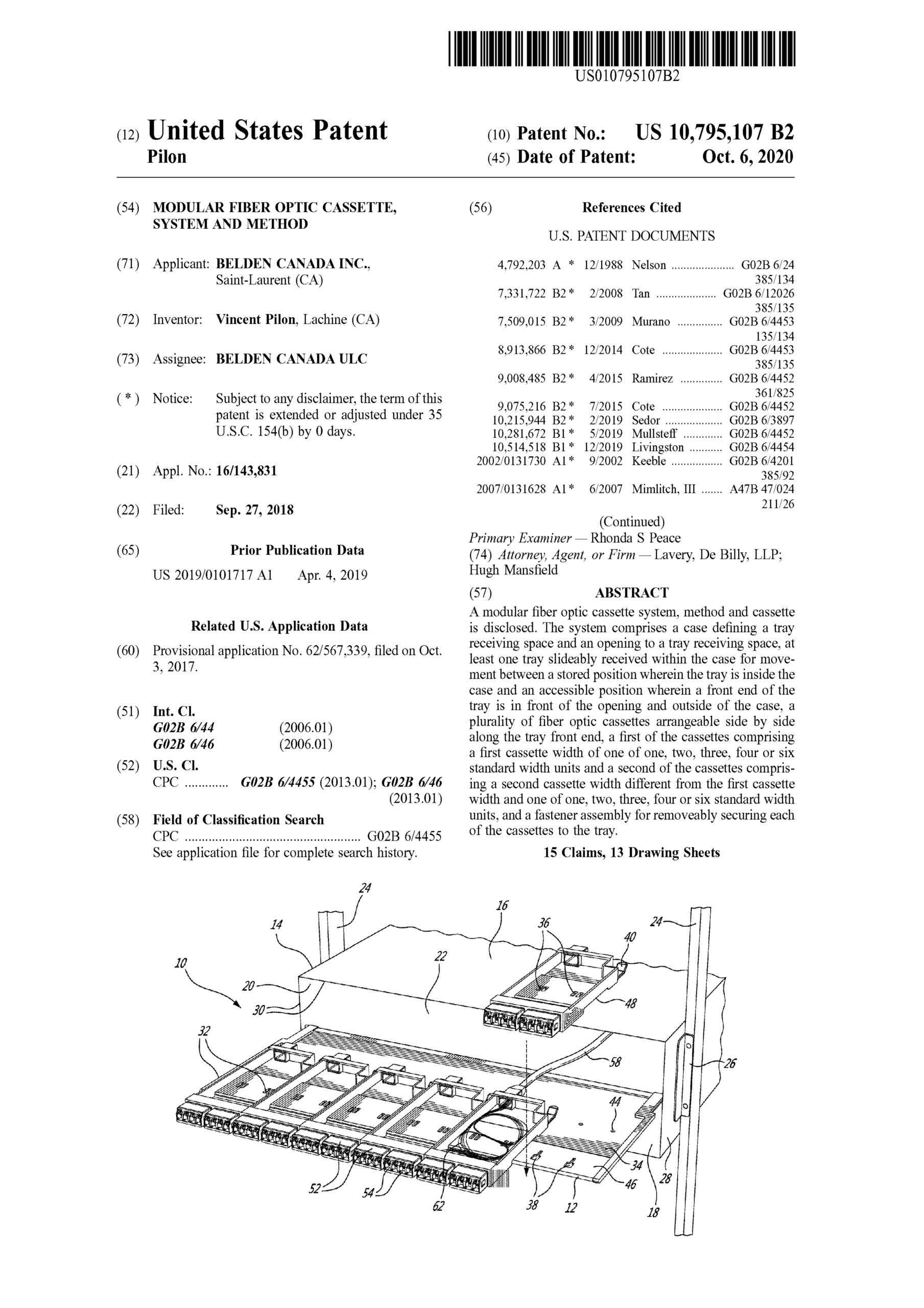
Modular fiber optic cassette, system and method

A modular fiber optic cassette system, method and cassette is disclosed. The system comprises a case defining a tray receiving space and an opening to a tray receiving space, at least one tray slideably received within the case for movement between a stored position wherein the tray is inside the case and an accessible position wherein a front end of the tray is in front of the opening and outside of the case, a plurality of fiber optic cassettes arrangeable side by side along the tray front end, a first of the cassettes comprising a first cassette width of one of one, two, three, four or six standard width units and a second of the cassettes comprising a second cassette width different from the first cassette width and one of one, two, three, four or six standard width units, and a fastener assembly for removeably securing each of the cassettes to the tray.

US Patent No. 10,782,489

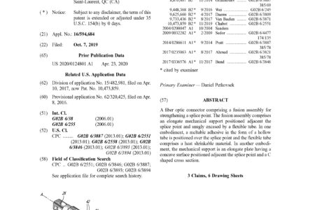
Fiber optic connector

A fiber optic connector comprising a fusion assembly for strengthening a splice point. The fusion assembly comprises an elongate mechanical support positioned adjacent the splice point and snugly encased by a flexible tube. In one embodiment, a meltable adhesive in the form of a hollow tube is positioned over the splice point and the flexible tube comprises a heat shrinkable material. In another embodiment, the mechanical support is an elongate plate having a concave surface positioned adjacent the splice point and a C shaped cross section.