US Patent No. 10,656,359

Fiber optic cassette system with slantable connector

A fiber optic cassette and system is disclosed. The cassette is mountable on a tray in parallel to and adjacent to at least one other like cassette. Each cassette comprises an housing having an axis, a first optic fiber connector-receiving receptacle along a housing front face for receiving at least one first optic fiber, a second optic fiber connector-receiving receptacle along a housing rear face for receiving at least one second optic fiber, and at least one third optic fiber within the housing, the third optic fibers interconnecting respective ones of the first optic fibers and the second optic fibers. The rear optic fiber connector-receiving receptacle is moveable in a horizontal plane between a first position wherein the rear receptacle is arranged at a first angle to the axis and a second position wherein the rear receptacle is arranged at a second angle to the axis.

US Patent No. 10,598,884

Fiber optic cassette system with releasable engagement

A modular fiber optic cassette and tray assembly is disclosed. The assembly comprises a tray engaging part which engages with a cassette engaging part on the tray and such that the cassettes may be arranged horizontally side by side on the trays. The cassettes are mounted to a front of a tray and such that a portion of each cassette is positioned in front of the tray. In an embodiment, a release mechanism such as a push button is provided on top of each cassette for disengaging the tray engaging part from the cassette engaging part. Still in another embodiment a plurality of trays and cassettes are provided stacked on top of one another.

US Patent No. 10,488,611

Dual direction fiber optic cassette system and fiber optic cassette

An optic fiber system for mounting in a rack, cassette and front plate are disclosed. A fiber optic cassette receives a pair of opposed rails on opposite inner surfaces of a housing. Catches on the fiber optic cassette comprise biased tabs which engage grooves within the rails thereby releasable securing the cassette into the housing. Catches may be provided at both ends of the cassette allowing the cassette to be inserted from either end of the housing. The cassette comprises removeable front plate which is secured to it using a snap fit. The removeable plate can be used either with the cassette or as a standalone within the housing.

US Patent No. 10,359,595

Slide and tilt tray, slide and tray using same

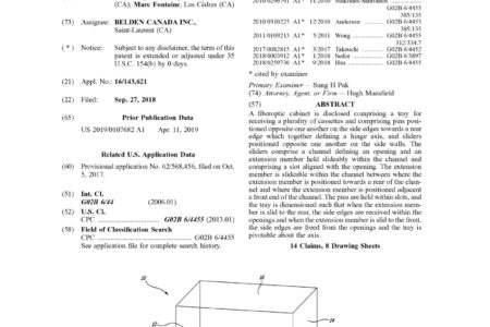
A fiberoptic cabinet is disclosed comprising a tray for receiving a plurality of cassettes and comprising pins positioned opposite one another on the side edges towards a rear edge which together defining a hinge axis, and sliders positioned opposite one another on the side walls. The sliders comprise a channel defining an opening and an extension member held slideably within the channel and comprising a slot aligned with the opening. The extension member is slideable within the channel between where the extension member is positioned towards a rear of the channel and where the extension member is positioned adjacent a front end of the channel. The pins are held within slots, and the tray is dimensioned such that when the extension member is slid to the rear, the side edges are received within the openings and when the extension member is slid to the front, the side edges are freed from the openings and the tray is pivotable about the axis.

US Patent No. 10,332,429

Labelling system for rackmount case for the accommodation of optical equipment

A rackmount case for the accommodation of optical equipment and labelling tag is disclosed. The case comprises a box like housing comprising an end defining a rectangular opening, labelling tags each comprising a rectangular tag plate and a plurality of hinge elements arranged along an edge of the rectangular tag plate. At least one labelling tag receiving slot is within the housing for receiving one of the labelling tags. The slot comprises an opening adjacent the housing opening and a plurality of hinge elements adjacent the slot opening. The labelling tags are moveable between a first position, wherein the tags are held within the slot, and a second position wherein the tags are outside of the slot and each of the hinge elements is engaged by a respective of the second hinge elements such that the tags are rotatable about an axis in parallel to the slot opening.

US Patent No. 10,185,108

Dual direction fiber optic cassette system and fiber optic cassette with removable standalone adaptor plate

An optic fiber system for mounting in a rack, cassette and front plate are disclosed. A fiber optic cassette receives a pair of opposed rails on opposite inner surfaces of a housing. Catches on the fiber optic cassette comprise biased tabs which engage grooves within the rails thereby releasable securing the cassette into the housing. Catches may be provided at both ends of the cassette allowing the cassette to be inserted from either end of the housing. The cassette comprises removable front plate which is secured to it using a snap fit. The removable plate can be used either with the cassette or as a standalone within the housing.

US Patent No. 10,185,101

Plug with rotatable release mechanism

A plug assembly comprising at least one elongate ferrule terminating an one optic fiber and arranged in parallel to an actuating axis, a plug housing the ferrule and such that an end of the ferrule is exposed at a forward end thereof, the forward end configured for insertion into a receptacle, an elongate release lever for releasably securing the plug housing to the receptacle, the lever comprising a first end fixed to the plug housing towards the forward end and a flexible free end, and an actuating assembly cooperating with the flexible free end and rotatable about the actuating axis between a position where the flexible free end is positioned spaced from the housing and a position where the flexible free end is positioned immediately adjacent the housing.

US Patent No. 9,841,574

Deformable latch mechanism for tray

A latch mechanism for retaining a tray in a selected one of a first, second position and third position. The latch mechanism comprises notches arranged on an inner surface of the housing along an axis parallel to a direction of travel of the tray, an elongate actuator on the tray and opposite the inner surface, the actuator comprising a first elongate member and a second elongate member, an inner end of the first elongate member connected to an inner end of the second elongate member at a connection point, a stop positioned at the connection point wherein the stop is biased laterally towards the inner surface. By increasing a distance between an outer end of the first elongate member and an outer end of the second elongate member the stop is moveable from an unactuated state wherein the stop is engageable by a selected one of the notches and such that the tray is retainable in a selected one of the first, second and third position, to an actuated state wherein the stop moves laterally against the biasing force away from the inner surface and such that the stop is no longer engageable by one of the notches.

US Patent No. 8,801,298

Slide actuated field installable fiber optic connector

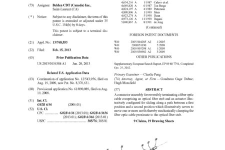
A connector assembly for reversibly terminating a fiber optic cable comprising an optical fiber stub and an actuator illustratively configured for sliding along a path between a first position and a second position which illustratively serves to move one or more anvils thereby mechanically clamping the fiber optic cable proximate to the optical fiber stub.

US Patent No. 8,075,198

Reversible fiber connector with mechanical sliding splice

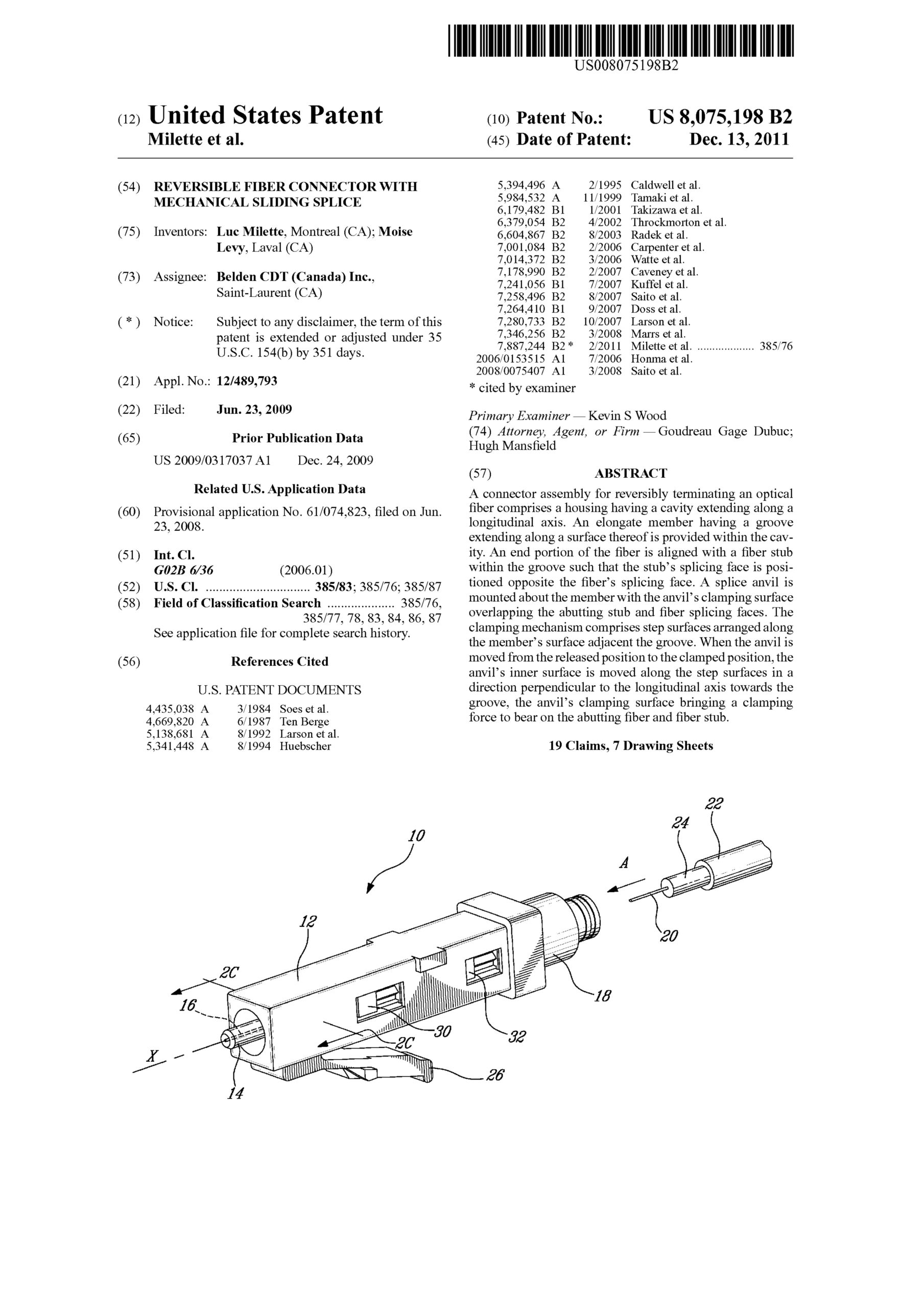
A connector assembly for reversibly terminating an optical fiber comprises a housing having a cavity extending along a longitudinal axis. An elongate member having a groove extending along a surface thereof is provided within the cavity. An end portion of the fiber is aligned with a fiber stub within the groove such that the stub’s splicing face is positioned opposite the fiber’s splicing face. A splice anvil is mounted about the member with the anvil’s clamping surface overlapping the abutting stub and fiber splicing faces. The clamping mechanism comprises step surfaces arranged along the member’s surface adjacent the groove. When the anvil is moved from the released position to the clamped position, the anvil’s inner surface is moved along the step surfaces in a direction perpendicular to the longitudinal axis towards the groove, the anvil’s clamping surface bringing a clamping force to bear on the abutting fiber and fiber stub.