US Patent No. 8,477,928

Crosstalk reducing conductor and contact configuration in a communication system

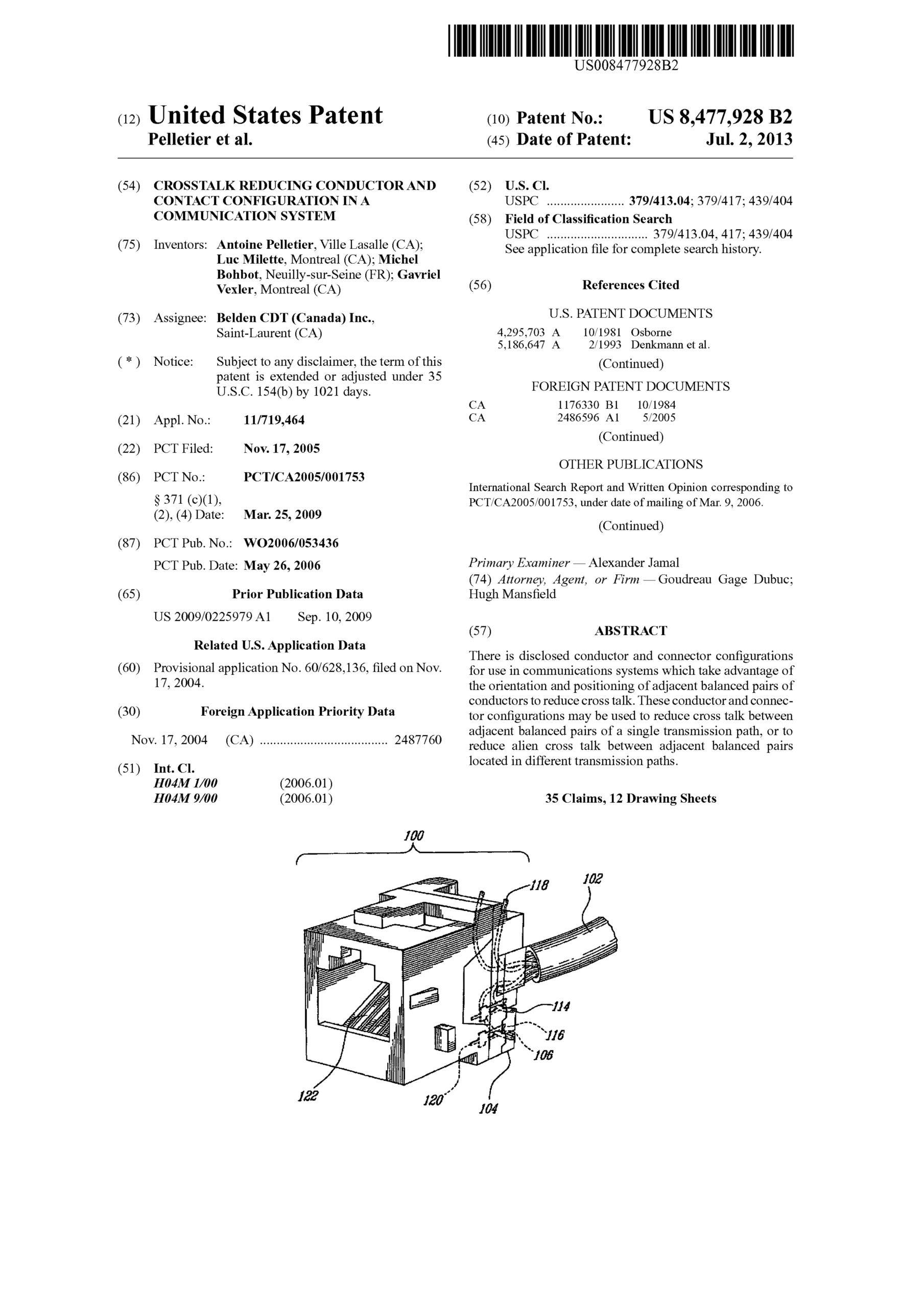
There is disclosed conductor and connector configurations for use in communications systems which take advantage of the orientation and positioning of adjacent balanced pairs of conductors to reduce cross talk. These conductor and connector configurations may be used to reduce cross talk between adjacent balanced pairs of a single transmission path, or to reduce alien cross talk between adjacent balanced pairs located in different transmission paths.
US Patent No. 7,837,513

Telecommunications connector

A contact element and mechanism for use in a connector, the connector comprising a socket adapted for receiving a cable plug comprising a terminal contact. The contact element and mechanism comprise a flexible dielectric substrate and a first conductive strip on a first surface of the substrate. When the plug is inserted into the socket, the terminal contact comes into contact with the conductive strip.
There is also provided a compensating connector for interconnection with a cable plug, the plug comprising a plurality of terminal contacts. The connector comprises a socket adapted for receiving the plug, a plurality of contact elements disposed in the socket, each of the contact elements comprising a conductive strip, and a compensation network comprised of a plurality of compensating elements. Each of the compensating elements is located adjacent to one of the contact elements. When the plug is inserted into the socket, each of the terminal contacts comes into contact with a predetermined one of the conductive strips.

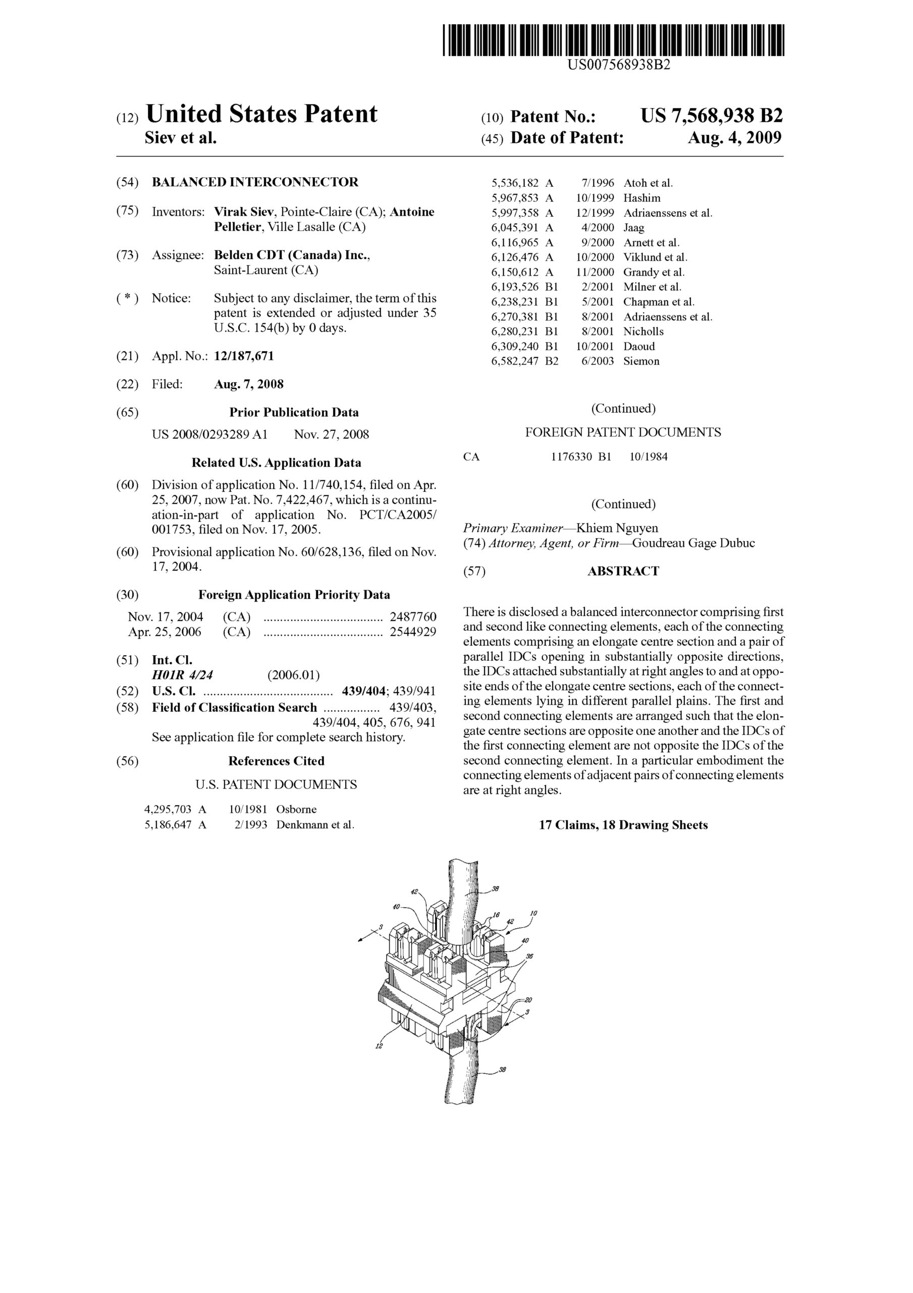
US Patent No. 7,568,938

Balanced interconnector

There is disclosed a balanced interconnector comprising first and second like connecting elements, each of the connecting elements comprising an elongate centre section and a pair of parallel IDCs opening in substantially opposite directions, the IDCs attached substantially at right angles to and at opposite ends of the elongate centre sections, each of the connecting elements lying in different parallel plains. The first and second connecting elements are arranged such that the elongate centre sections are opposite one another and the IDCs of the first connecting element are not opposite the IDCs of the second connecting element. In a particular embodiment the connecting elements of adjacent pairs of connecting elements are at right angles.

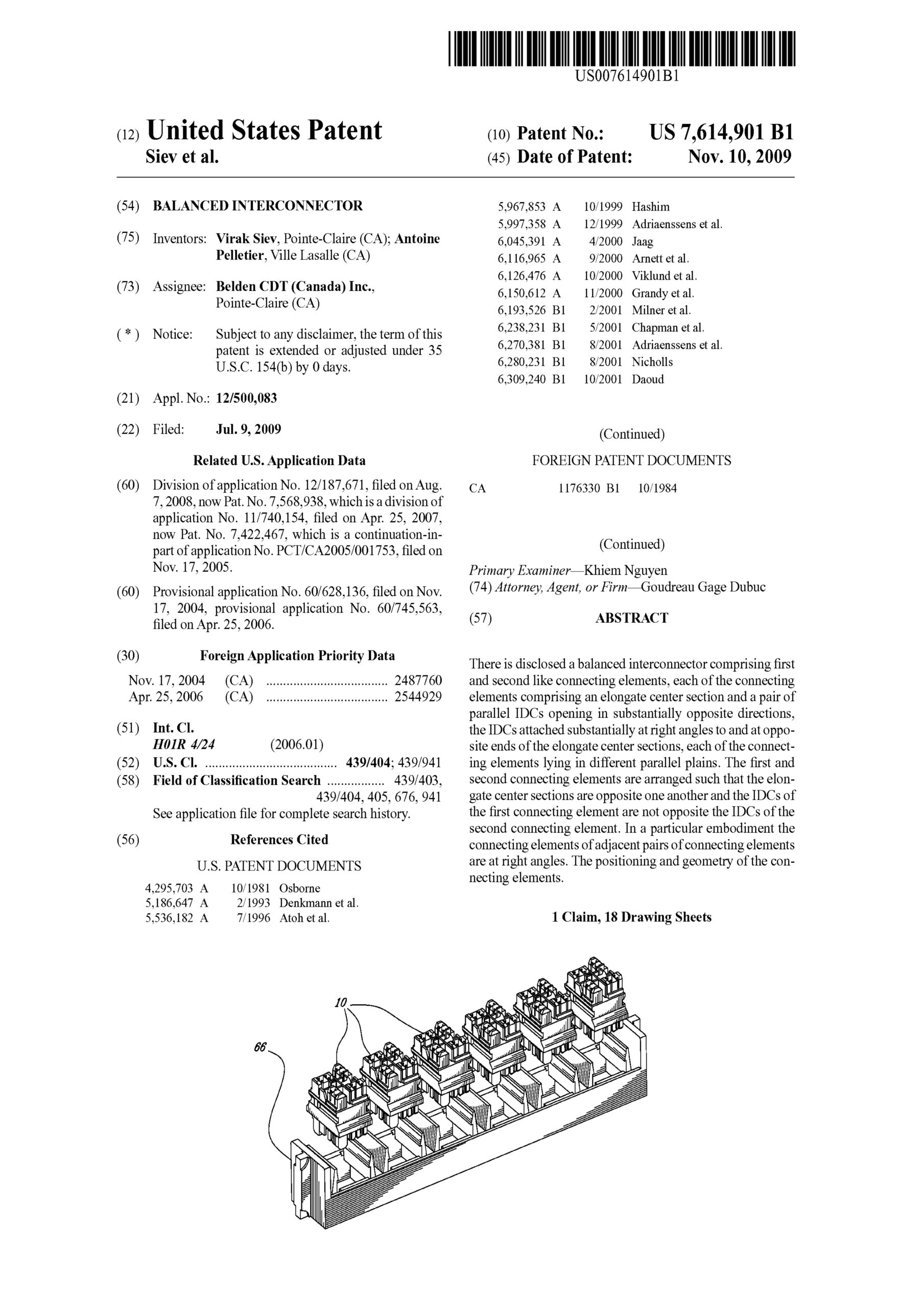
US Patent No. 7,614,901

Balanced interconnector

There is disclosed a balanced interconnector comprising first and second like connecting elements, each of the connecting elements comprising an elongate center section and a pair of parallel IDCs opening in substantially opposite directions, the IDCs attached substantially at right angles to and at opposite ends of the elongate center sections, each of the connecting elements lying in different parallel plains. The first and second connecting elements are arranged such that the elongate center sections are opposite one another and the IDCs of the first connecting element are not opposite the IDCs of the second connecting element. In a particular embodiment the connecting elements of adjacent pairs of connecting elements are at right angles. The positioning and geometry of the connecting elements.

US Patent No. 7,422,467

Balanced interconnector

There is disclosed a balanced interconnector comprising first and second like connecting elements, each of the connecting elements comprising an elongate center section and a pair of parallel IDCs opening in substantially opposite directions, the IDCs attached substantially at right angles to and at opposite ends of the elongate center sections, each of the connecting elements lying in different parallel plains. The first and second connecting elements are arranged such that the elongate center sections are opposite one another and the IDCs of the first connecting element are not opposite the IDCs of the second connecting element. In a particular embodiment the connecting elements of adjacent pairs of connecting elements are at right angles. The positioning and geometry of the connecting elements.

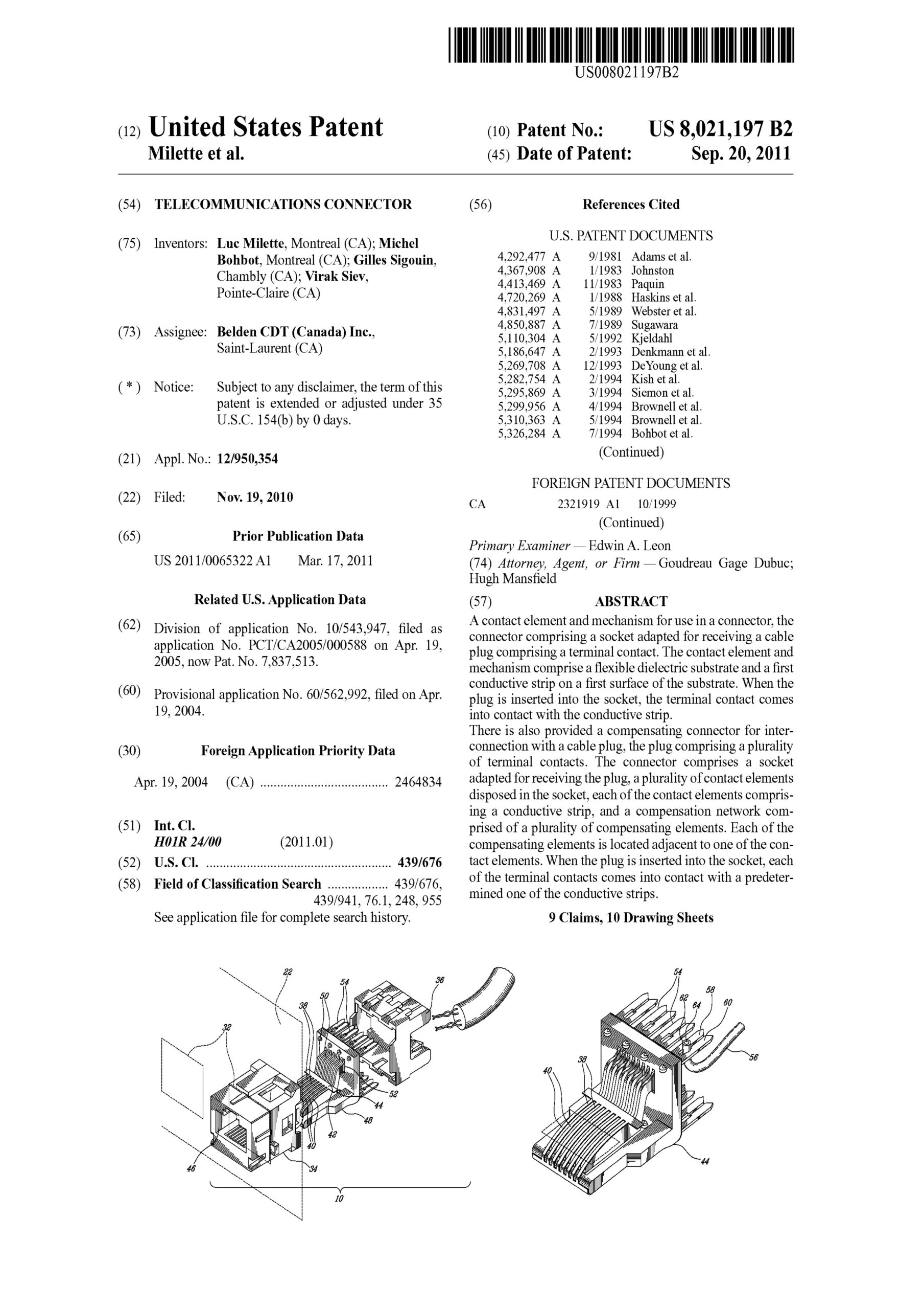
US Patent No. 8,021,197

Telecommunications connector

A contact element and mechanism for use in a connector, the connector comprising a socket adapted for receiving a cable plug comprising a terminal contact. The contact element and mechanism comprise a flexible dielectric substrate and a first conductive strip on a first surface of the substrate. When the plug is inserted into the socket, the terminal contact comes into contact with the conductive strip.
There is also provided a compensating connector for interconnection with a cable plug, the plug comprising a plurality of terminal contacts. The connector comprises a socket adapted for receiving the plug, a plurality of contact elements disposed in the socket, each of the contact elements comprising a conductive strip, and a compensation network comprised of a plurality of compensating elements. Each of the compensating elements is located adjacent to one of the contact elements. When the plug is inserted into the socket, each of the terminal contacts comes into contact with a predetermined one of the conductive strips.

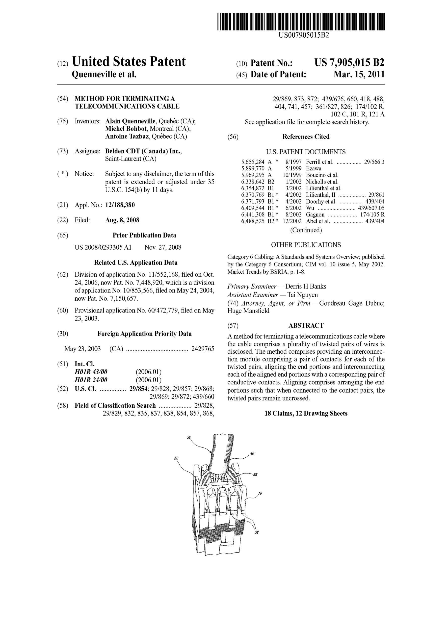
US Patent No. 7,905,015

Method for terminating a telecommunications cable

A method for terminating a telecommunications cable where the cable comprises a plurality of twisted pairs of wires is disclosed. The method comprises providing an interconnection module comprising a pair of contacts for each of the twisted pairs, aligning the end portions and interconnecting each of the aligned end portions with a corresponding pair of conductive contacts. Aligning comprises arranging the end portions such that when connected to the contact pairs, the twisted pairs remain uncrossed.

US Patent No. 7,150,657

Wire lead guide and method for terminating a communications cable

A method for terminating a telecommunications cable where the cable comprises a plurality of twisted pairs of wires. The method comprises the steps providing an interconnection module comprising a pair of contacts for each of the twisted pairs, aligning the end portions and interconnecting each of the aligned end portions with a corresponding pair of conductive contacts. The aligning step comprises arranging the end portions such that when connected to the contact pairs, the twisted pairs remain uncrossed.
A wire lead guide for isolating the end portions of a plurality twisted pairs of wires an a connector assembly using the same. The guide comprises a guide body and a plurality of non-intersecting passageways through the body. Each of the passageways is comprised of an entrance and an exit. The end portions of one of the twisted pairs are inserted through a corresponding one of the passageways. The passageways isolate the twisted pairs of wires from one another.

US Patent No. 7,448,920

Wire Lead Guide and Method for Terminating a Communications Cable

A method for terminating a telecommunications cable where the cable comprises a plurality of twisted pairs of wires. The method comprises the steps providing an interconnection module comprising a pair of contacts for each of the twisted pairs, aligning the end portions and interconnecting each of the aligned end portions with a corresponding pair of conductive contacts. The aligning step comprises arranging the end portions such that when connected to the contact pairs, the twisted pairs remain uncrossed.
A wire lead guide for isolating the end portions of a plurality twisted pairs of wires and a connector assembly using the same. The guide comprises a guide body and a plurality of non-intersecting passageways through the body. Each of the passageways is comprised of an entrance and an exit. The end portions of one of the twisted pairs are inserted through a corresponding one of the passageways. The passageways isolate the twisted pairs of wires from one another.