US Patent No. 10,186,797

Coupler connector and cable terminator with side contacts

An assembly comprising a cable terminator comprising a wire guide, a cube shaped securing cap comprising an open end for installation over the wire guide, and pairs of piercing contacts for piercing respective conductors of the cable. When assembled, an outer end of each of the piercing contacts is exposed on an outer surface of a respective securing cap sidewall. The assembly also comprises a coupler connector comprising one of a modular (for example RJ-45 compatible) socket or a modular (for example RJ-45 compatible) plug, a rearward surface comprising a cable terminator receiving socket, wherein pairs of contacts are exposed along at least one side wall of the socket, and further wherein each of a plurality of the tines in the modular socket or the terminal contacts of the plug is interconnected with a respective one of the contacts.
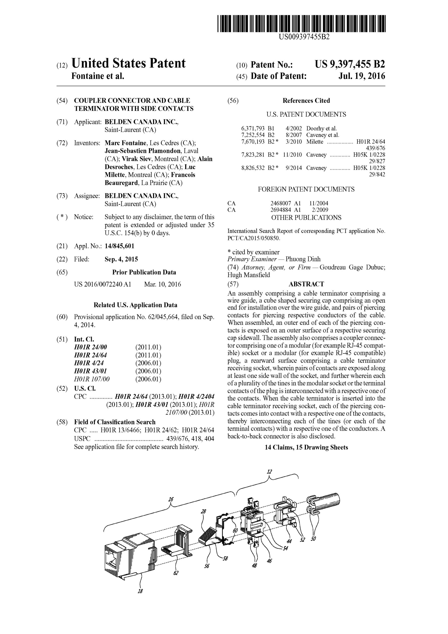
US Patent No. 9,397,455

Coupler connector and cable terminator with side contacts

An assembly comprising a cable terminator comprising a wire guide, a cube shaped securing cap comprising an open end for installation over the wire guide, and pairs of piercing contacts for piercing respective conductors of the cable. When assembled, an outer end of each of the piercing contacts is exposed on an outer surface of a respective securing cap sidewall. The assembly also comprises a coupler connector comprising one of a modular (for example RJ-45 compatible) socket or a modular (for example RJ-45 compatible) plug, a rearward surface comprising a cable terminator receiving socket, wherein pairs of contacts are exposed along at least one side wall of the socket, and further wherein each of a plurality of the tines in the modular socket or the terminal contacts of the plug is interconnected with a respective one of the contacts. When the cable terminator is inserted into the cable terminator receiving socket, each of the piercing contacts comes into contact with a respective one of the contacts, thereby interconnecting each of the tines (or each of the terminal contacts) with a respective one of the conductors. A back-to-back connector is also disclosed.
US Patent No. 9,865,960

Coupler connector and cable terminator with side contacts

An assembly comprising a cable terminator comprising a wire guide, a cube shaped securing cap comprising an open end for installation over the wire guide, and pairs of piercing contacts for piercing respective conductors of the cable. When assembled, an outer end of each of the piercing contacts is exposed on an outer surface of a respective securing cap sidewall. The assembly also comprises a coupler connector comprising one of a modular (for example RJ-45 compatible) socket or a modular (for example RJ-45 compatible) plug, a rearward surface comprising a cable terminator receiving socket, wherein pairs of contacts are exposed along at least one side wall of the socket, and further wherein each of a plurality of the tines in the modular socket or the terminal contacts of the plug is interconnected with a respective one of the contacts. When the cable terminator is inserted into the cable terminator receiving socket, each of the piercing contacts comes into contact with a respective one of the contacts, thereby interconnecting each of the tines (or each of the terminal contacts) with a respective one of the conductors. A back-to-back connector is also disclosed.
US Patent No. 9,413,125

Coupler connector and cable terminator with end contacts

An assembly comprising a cable terminator comprising an elongate wire guide comprising a top end and four conductor pair receiving channels, and a securing cap configured for installation over the top end and comprising four pairs of piercing contacts exposed on an upper surface is disclosed. Each pair of the piercing contacts are interconnected with a respective conductor pair, and a coupler connector comprising a forward surface comprising an RJ-45 compatible socket, wherein tines are exposed within the socket and a rearward surface comprising a cable terminator receiving socket. Pairs of contacts are exposed on an end wall of the socket. Each of the tines is interconnected with a respective one of the contacts. When the cable terminator is inserted into the cable terminator receiving socket, the upper surface of the securing cap is positioned against the end wall and each of the piercing contacts comes into contact with a respective one of the contacts, thereby interconnecting each of the tines with one of the conductors.
US Patent No. 8,801,298

Slide actuated field installable fiber optic connector

A connector assembly for reversibly terminating a fiber optic cable comprising an optical fiber stub and an actuator illustratively configured for sliding along a path between a first position and a second position which illustratively serves to move one or more anvils thereby mechanically clamping the fiber optic cable proximate to the optical fiber stub.

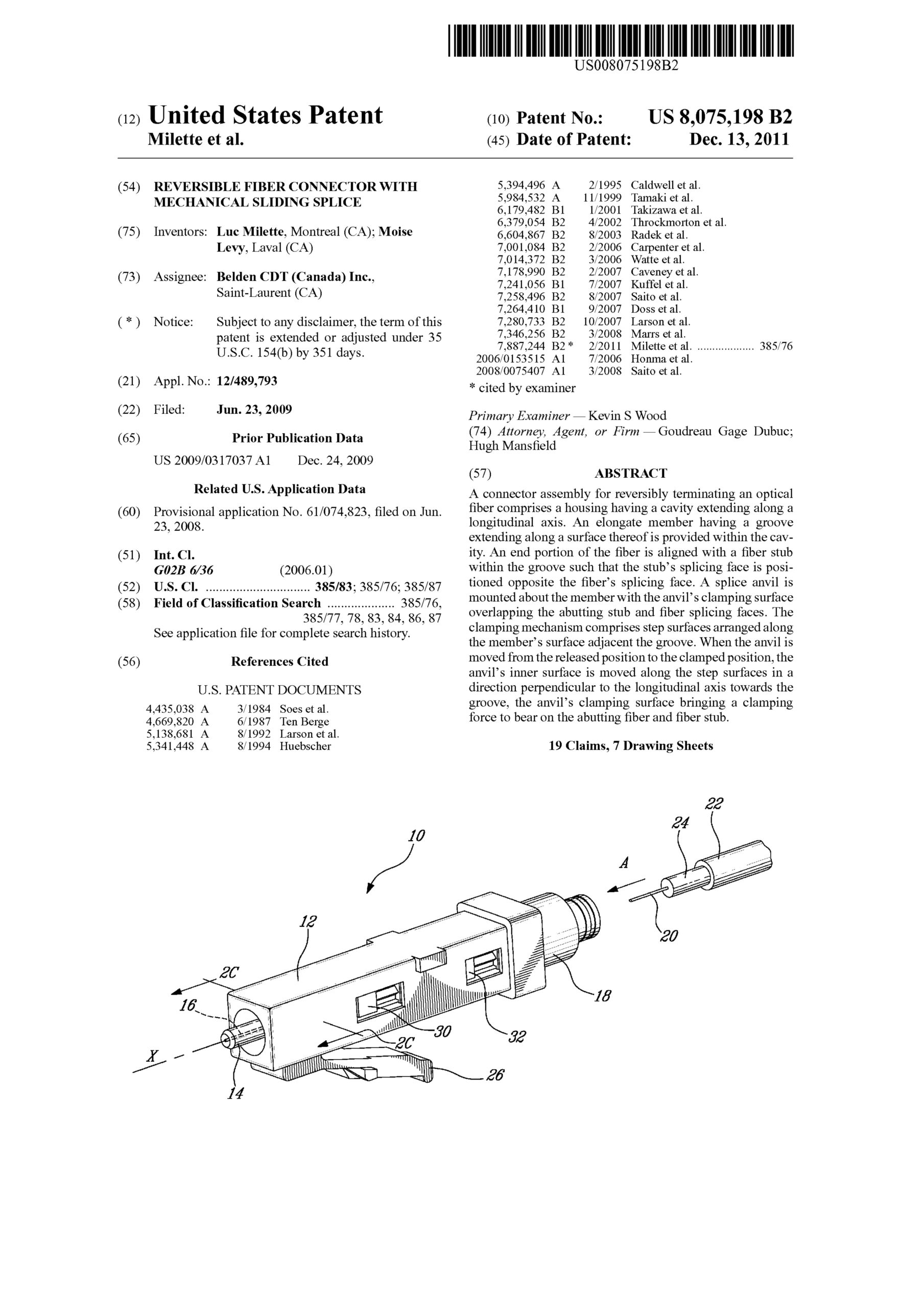
US Patent No. 8,075,198

Reversible fiber connector with mechanical sliding splice

A connector assembly for reversibly terminating an optical fiber comprises a housing having a cavity extending along a longitudinal axis. An elongate member having a groove extending along a surface thereof is provided within the cavity. An end portion of the fiber is aligned with a fiber stub within the groove such that the stub’s splicing face is positioned opposite the fiber’s splicing face. A splice anvil is mounted about the member with the anvil’s clamping surface overlapping the abutting stub and fiber splicing faces. The clamping mechanism comprises step surfaces arranged along the member’s surface adjacent the groove. When the anvil is moved from the released position to the clamped position, the anvil’s inner surface is moved along the step surfaces in a direction perpendicular to the longitudinal axis towards the groove, the anvil’s clamping surface bringing a clamping force to bear on the abutting fiber and fiber stub.

US Patent No. 8,167,662

Cable comprising connector with insulation piercing contacts

There is disclosed a connector and method for terminating a cable comprised twisted pairs of conductors. In one aspect of the invention the connector comprises a wire lead guide for arranging the twisted pairs of conductors and a plurality of piercing contacts which interconnect with respective ones of the twisted pairs of conductors when the wire guide is secured to the module. In a further aspect of the invention the wire lead guide ensures that the spacing between the conductors of a particular twisted pair is maintained, thereby improving the performance of the subsequent assembly.

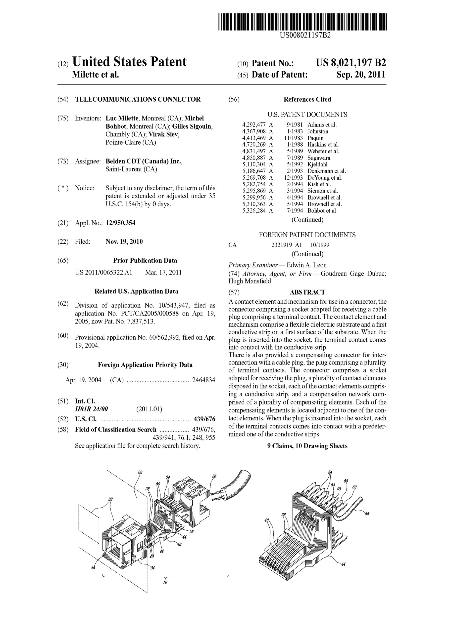
US Patent No. 8,021,197

Telecommunications connector

A contact element and mechanism for use in a connector, the connector comprising a socket adapted for receiving a cable plug comprising a terminal contact. The contact element and mechanism comprise a flexible dielectric substrate and a first conductive strip on a first surface of the substrate. When the plug is inserted into the socket, the terminal contact comes into contact with the conductive strip.
There is also provided a compensating connector for interconnection with a cable plug, the plug comprising a plurality of terminal contacts. The connector comprises a socket adapted for receiving the plug, a plurality of contact elements disposed in the socket, each of the contact elements comprising a conductive strip, and a compensation network comprised of a plurality of compensating elements. Each of the compensating elements is located adjacent to one of the contact elements. When the plug is inserted into the socket, each of the terminal contacts comes into contact with a predetermined one of the conductive strips.

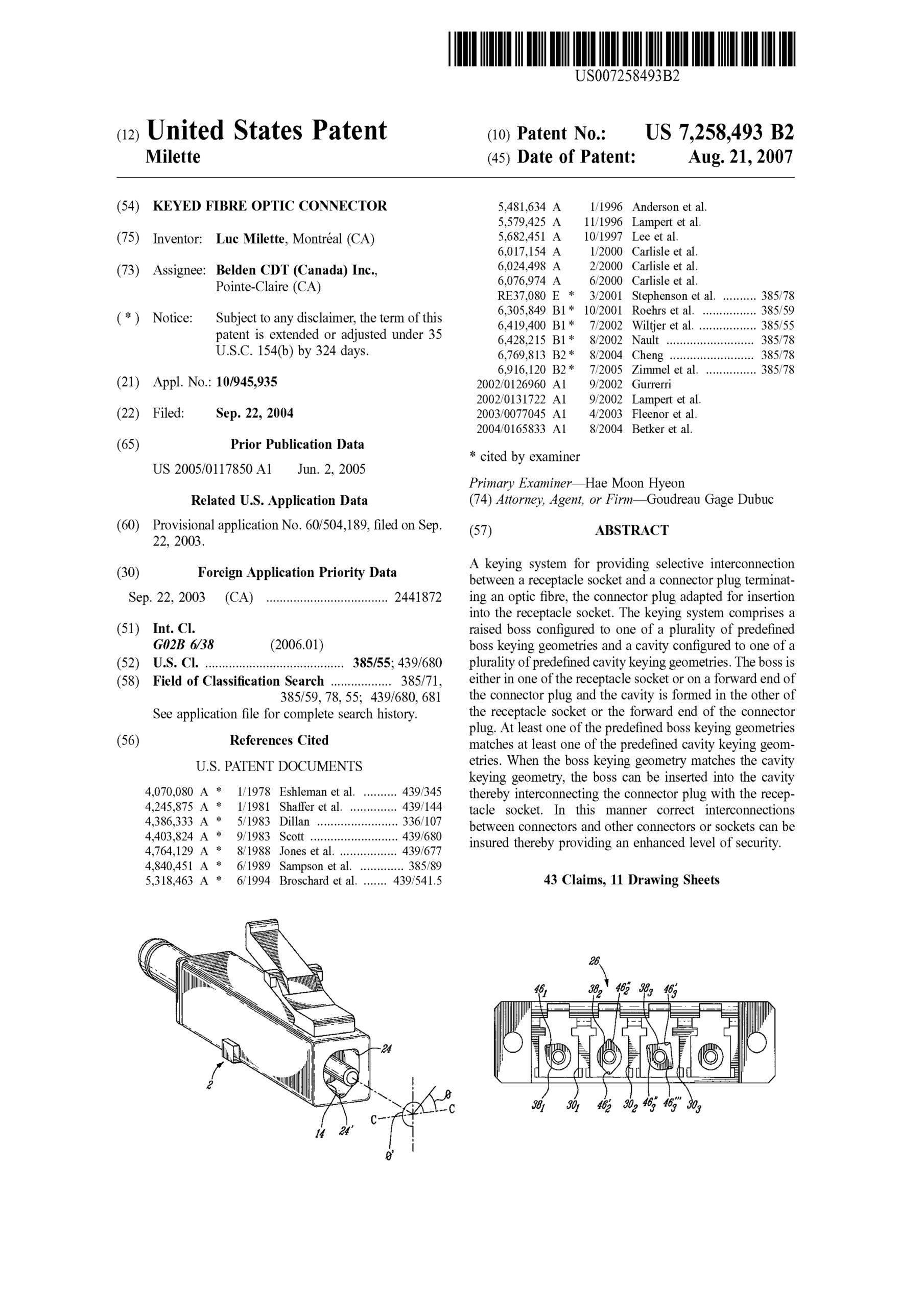
US Patent No. 7,258,493

Keyed fibre optic connector

A keying system for providing selective interconnection between a receptacle socket and a connector plug terminating an optic fibre, the connector plug adapted for insertion into the receptacle socket. The keying system comprises a raised boss configured to one of a plurality of predefined boss keying geometries and a cavity configured to one of a plurality of predefined cavity keying geometries. The boss is either in one of the receptacle socket or on a forward end of the connector plug and the cavity is formed in the other of the receptacle socket or the forward end of the connector plug. At least one of the predefined boss keying geometries matches at least one of the predefined cavity keying geometries. When the boss keying geometry matches the cavity keying geometry, the boss can be inserted into the cavity thereby interconnecting the connector plug with the receptacle socket. In this manner correct interconnections between connectors and other connectors or sockets can be insured thereby providing an enhanced level of security.

US Patent No. 7,699,533

Back-to-back receptacle

A back-to-back receptacle and system for providing selective interconnection between a pair of optic fibres. The system comprises a receptacle comprising a pair of back-to-back receptacle sockets, with at least a first of the sockets configured to one of a plurality of predefined receptacle keying geometries, a first connector plug terminating the first optic fibre, the plug adapted for insertion into the first receptacle socket, the plug configured to one of a plurality of predefined connector keying geometries and a second connector plug terminating the second optic fibre, the plug adapted for insertion into a second of the back-to-back receptacle sockets. At least one of the predefined connector keying geometries matches at least one of the predefined receptacle keying geometries. When the receptacle keying geometry of the first receptacle socket corresponds to the connector keying geometry of the first plug and optionally the receptacle geometry of the second of the back-to-back receptacle sockets corresponds to the connector keying geometry of the second plug, the first plug can be inserted in the first socket and the second plug can be inserted in the second socket bringing the first optic fibre into axial alignment with the second optic fibre.