US Patent No. 10,186,797

Coupler connector and cable terminator with side contacts
An assembly comprising a cable terminator comprising a wire guide, a cube shaped securing cap comprising an open end for installation over the wire guide, and pairs of piercing contacts for piercing respective conductors of the cable. When assembled, an outer end of each of the piercing contacts is exposed on an outer surface of a respective securing cap sidewall. The assembly also comprises a coupler connector comprising one of a modular (for example RJ-45 compatible) socket or a modular (for example RJ-45 compatible) plug, a rearward surface comprising a cable terminator receiving socket, wherein pairs of contacts are exposed along at least one side wall of the socket, and further wherein each of a plurality of the tines in the modular socket or the terminal contacts of the plug is interconnected with a respective one of the contacts.

US Patent No. 9,397,455

Coupler connector and cable terminator with side contacts
An assembly comprising a cable terminator comprising a wire guide, a cube shaped securing cap comprising an open end for installation over the wire guide, and pairs of piercing contacts for piercing respective conductors of the cable. When assembled, an outer end of each of the piercing contacts is exposed on an outer surface of a respective securing cap sidewall. The assembly also comprises a coupler connector comprising one of a modular (for example RJ-45 compatible) socket or a modular (for example RJ-45 compatible) plug, a rearward surface comprising a cable terminator receiving socket, wherein pairs of contacts are exposed along at least one side wall of the socket, and further wherein each of a plurality of the tines in the modular socket or the terminal contacts of the plug is interconnected with a respective one of the contacts. When the cable terminator is inserted into the cable terminator receiving socket, each of the piercing contacts comes into contact with a respective one of the contacts, thereby interconnecting each of the tines (or each of the terminal contacts) with a respective one of the conductors. A back-to-back connector is also disclosed.

US Patent No. 9,865,960

Coupler connector and cable terminator with side contacts

An assembly comprising a cable terminator comprising a wire guide, a cube shaped securing cap comprising an open end for installation over the wire guide, and pairs of piercing contacts for piercing respective conductors of the cable. When assembled, an outer end of each of the piercing contacts is exposed on an outer surface of a respective securing cap sidewall. The assembly also comprises a coupler connector comprising one of a modular (for example RJ-45 compatible) socket or a modular (for example RJ-45 compatible) plug, a rearward surface comprising a cable terminator receiving socket, wherein pairs of contacts are exposed along at least one side wall of the socket, and further wherein each of a plurality of the tines in the modular socket or the terminal contacts of the plug is interconnected with a respective one of the contacts. When the cable terminator is inserted into the cable terminator receiving socket, each of the piercing contacts comes into contact with a respective one of the contacts, thereby interconnecting each of the tines (or each of the terminal contacts) with a respective one of the conductors. A back-to-back connector is also disclosed.

US Patent No. 9,413,125

Coupler connector and cable terminator with end contacts
An assembly comprising a cable terminator comprising an elongate wire guide comprising a top end and four conductor pair receiving channels, and a securing cap configured for installation over the top end and comprising four pairs of piercing contacts exposed on an upper surface is disclosed. Each pair of the piercing contacts are interconnected with a respective conductor pair, and a coupler connector comprising a forward surface comprising an RJ-45 compatible socket, wherein tines are exposed within the socket and a rearward surface comprising a cable terminator receiving socket. Pairs of contacts are exposed on an end wall of the socket. Each of the tines is interconnected with a respective one of the contacts. When the cable terminator is inserted into the cable terminator receiving socket, the upper surface of the securing cap is positioned against the end wall and each of the piercing contacts comes into contact with a respective one of the contacts, thereby interconnecting each of the tines with one of the conductors.

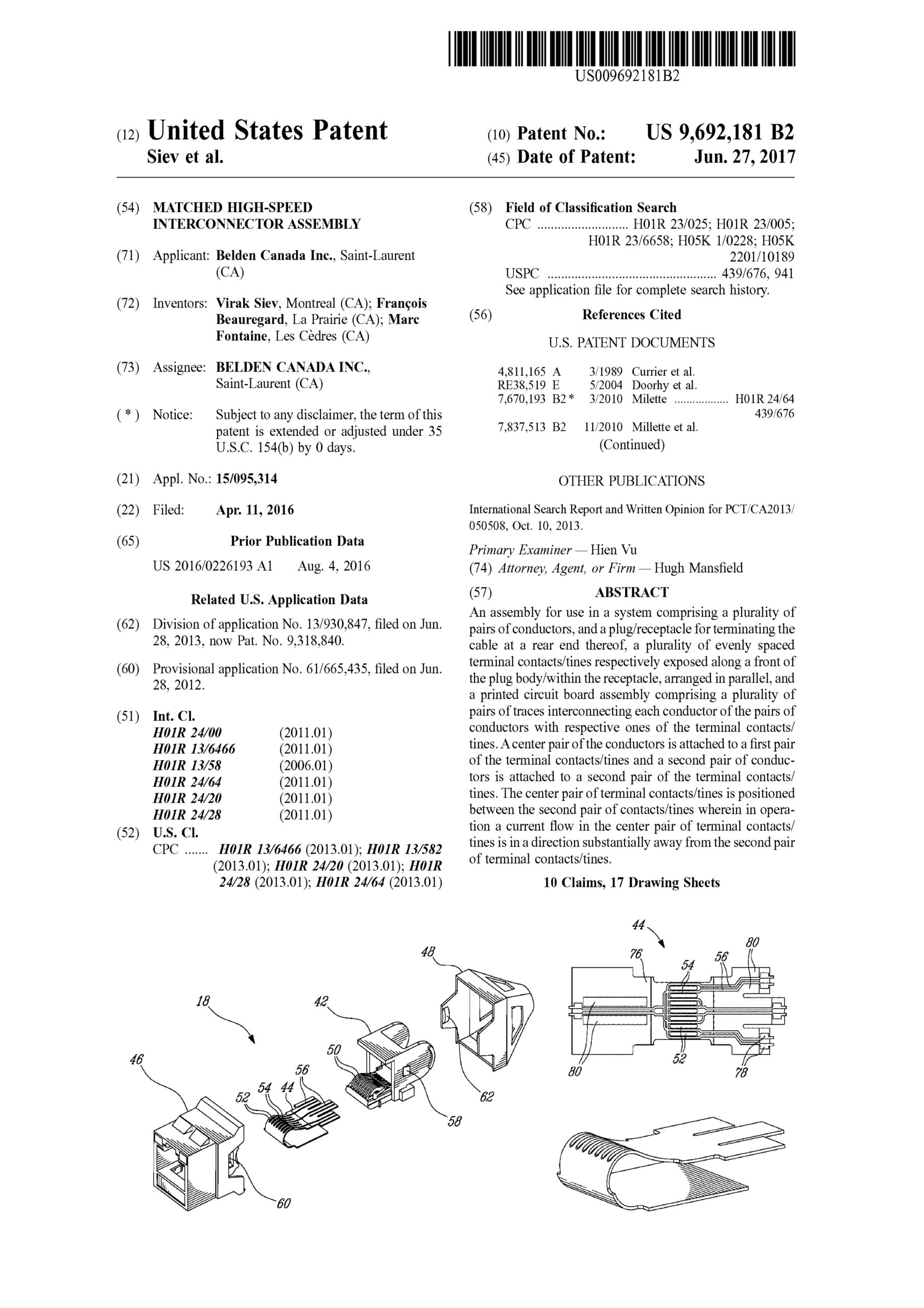
US Patent No. 9,692,181

Matched high-speed interconnector assembly
An assembly for use in a system comprising a plurality of pairs of conductors, and a plug/receptacle for terminating the cable at a rear end thereof, a plurality of evenly spaced terminal contacts/tines respectively exposed along a front of the plug body/within the receptacle, arranged in parallel, and a printed circuit board assembly comprising a plurality of pairs of traces interconnecting each conductor of the pairs of conductors with respective ones of the terminal contacts/tines. A center pair of the conductors is attached to a first pair of the terminal contacts/tines and a second pair of conductors is attached to a second pair of the terminal contacts/tines. The center pair of terminal contacts/tines is positioned between the second pair of contacts/tines wherein in operation a current flow in the center pair of terminal contacts/tines is in a direction substantially away from the second pair of terminal contacts/tines.

US Patent No. 8,167,662

Cable comprising connector with insulation piercing contacts
There is disclosed a connector and method for terminating a cable comprised twisted pairs of conductors. In one aspect of the invention the connector comprises a wire lead guide for arranging the twisted pairs of conductors and a plurality of piercing contacts which interconnect with respective ones of the twisted pairs of conductors when the wire guide is secured to the module. In a further aspect of the invention the wire lead guide ensures that the spacing between the conductors of a particular twisted pair is maintained, thereby improving the performance of the subsequent assembly.

US Patent No. 8,021,197

Telecommunications connector

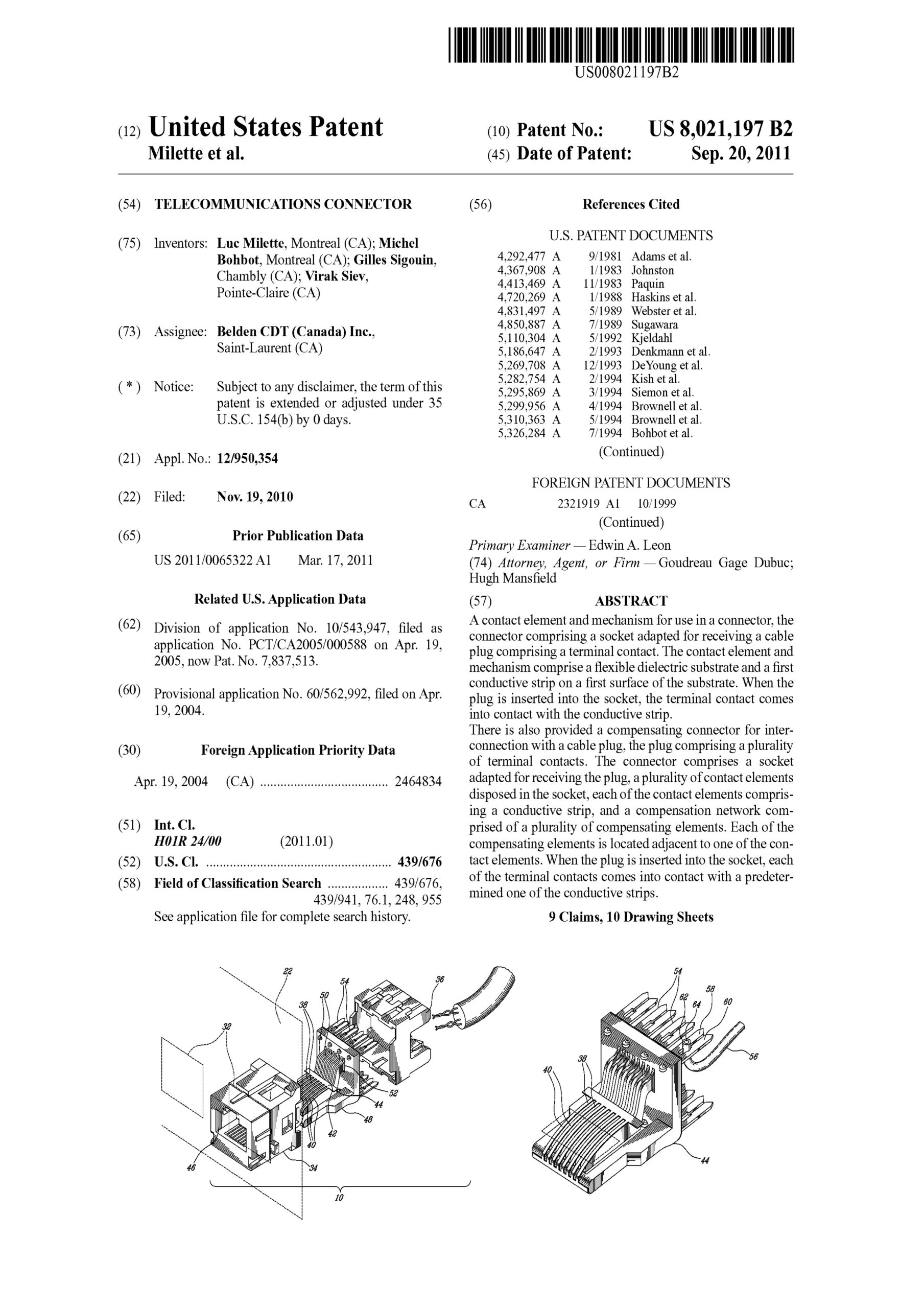
A contact element and mechanism for use in a connector, the connector comprising a socket adapted for receiving a cable plug comprising a terminal contact. The contact element and mechanism comprise a flexible dielectric substrate and a first conductive strip on a first surface of the substrate. When the plug is inserted into the socket, the terminal contact comes into contact with the conductive strip.
There is also provided a compensating connector for interconnection with a cable plug, the plug comprising a plurality of terminal contacts. The connector comprises a socket adapted for receiving the plug, a plurality of contact elements disposed in the socket, each of the contact elements comprising a conductive strip, and a compensation network comprised of a plurality of compensating elements. Each of the compensating elements is located adjacent to one of the contact elements. When the plug is inserted into the socket, each of the terminal contacts comes into contact with a predetermined one of the conductive strips.

US Patent No. 10,103,493

Method of maintaining cross talk in different zones of an assembly for interconnecting a cable

A method of manufacturing a connector and assembly of a cabling category and comprising two mating zones connected by an intermediate zone. Each of the zones is manufactured such that Near End Cross Talk (NEXT) resulting from transmission of the high frequency signal across each zone is below a specified amount chosen such that NEXT introduced by a high frequency signal transmission between via all the zones is below a level as specified for the cabling category.

US Patent No. 9,318,840

Matched High-Speed Interconnector Assembly

An assembly for use in a system comprising a plurality of pairs of conductors, and a plug/receptacle for terminating the cable at a rear end thereof, a plurality of evenly spaced terminal contacts/tines respectively exposed along a front of the plug body/within the receptacle, arranged in parallel, and a printed circuit board assembly comprising a plurality of pairs of traces interconnecting each conductor of the pairs of conductors with respective ones of the terminal contacts/tines. A center pair of the conductors is attached to a first pair of the terminal contacts/tines and a second pair of conductors is attached to a second pair of the terminal contacts/tines. The center pair of terminal contacts/tines is positioned between the second pair of contacts/tines wherein in operation a current flow in the center pair of terminal contacts/tines is in a direction substantially away from the second pair of terminal contacts/tines.

https://patents.google.com/patent/US9318840B2/en